Sunday, August 29, 2010

Citation I Refurb - Final Assembly, Part II

Well, this is it.  Final Assembly - Part II.  After this post the Citation I rebuild project will be complete.  That won't be the end of my Citation audio posts.  But this post should do it for the rebuild.

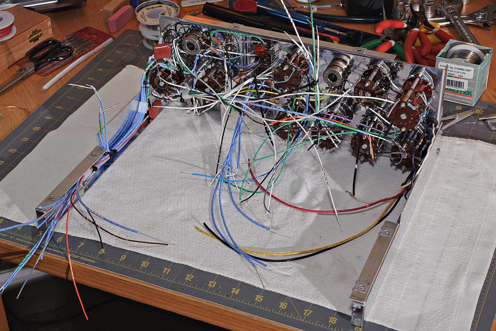
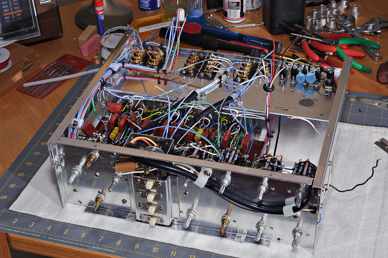
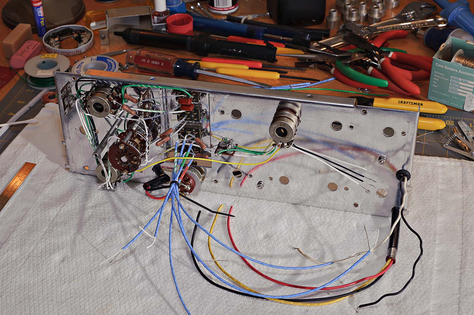
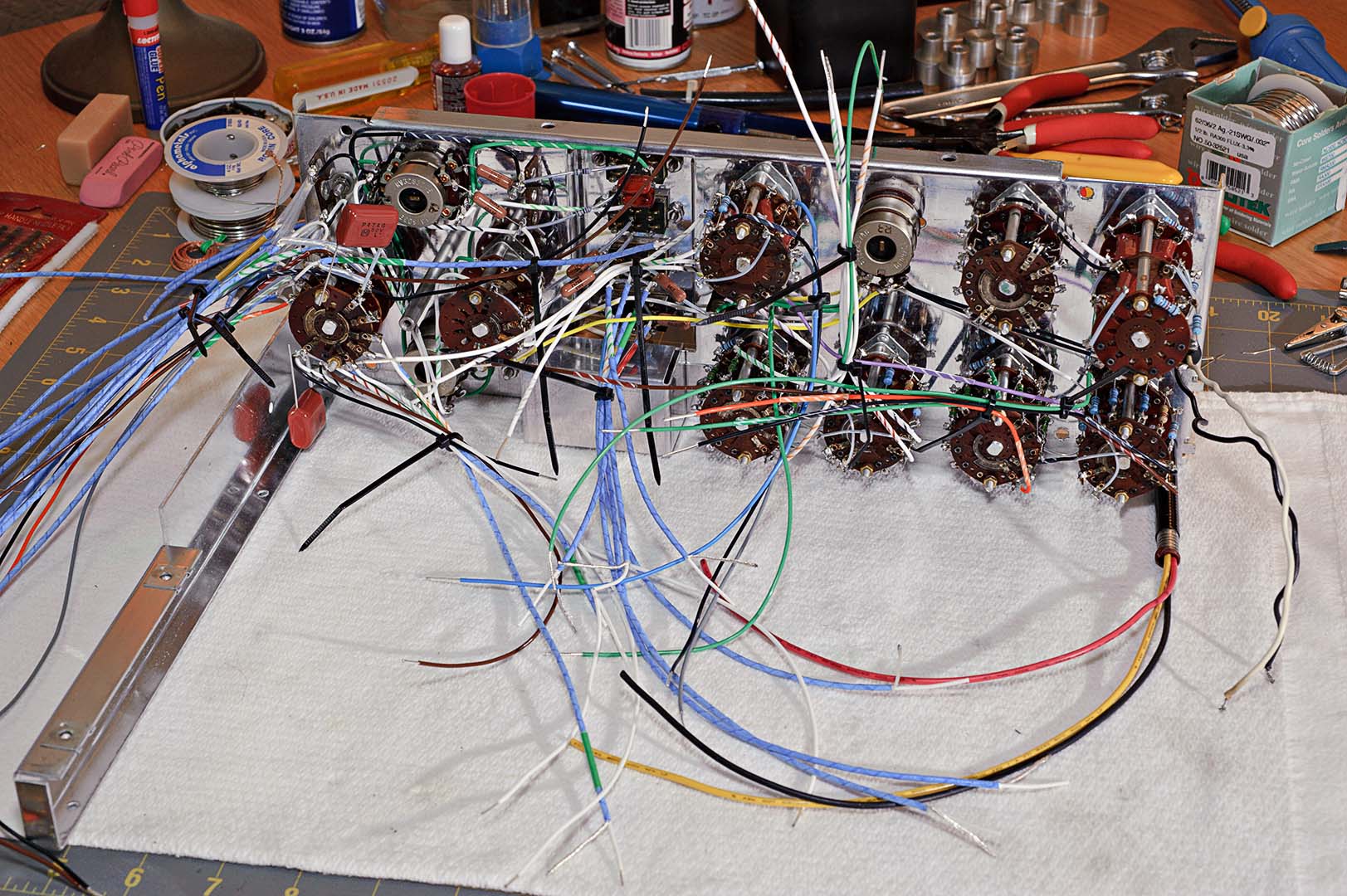
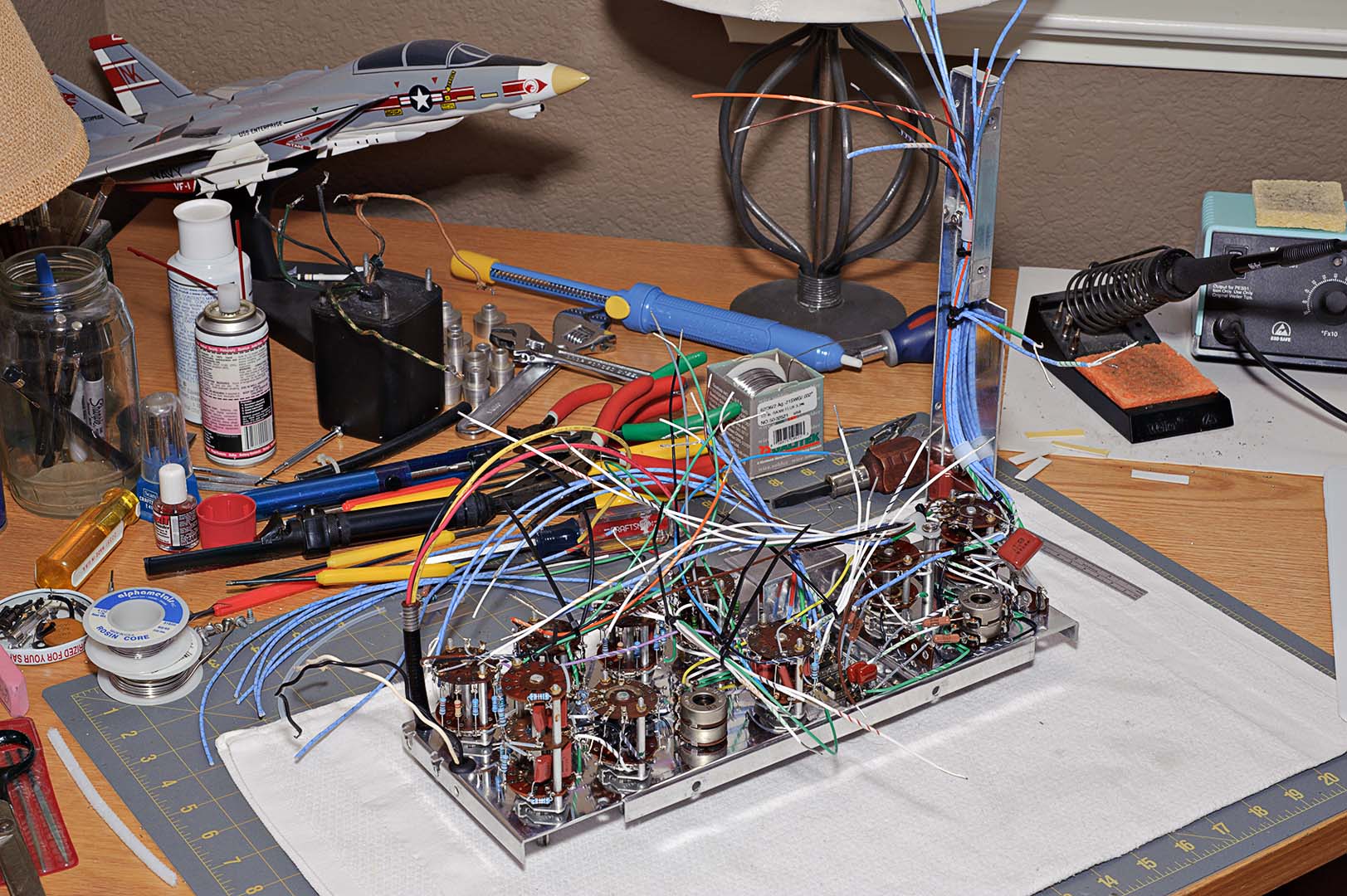
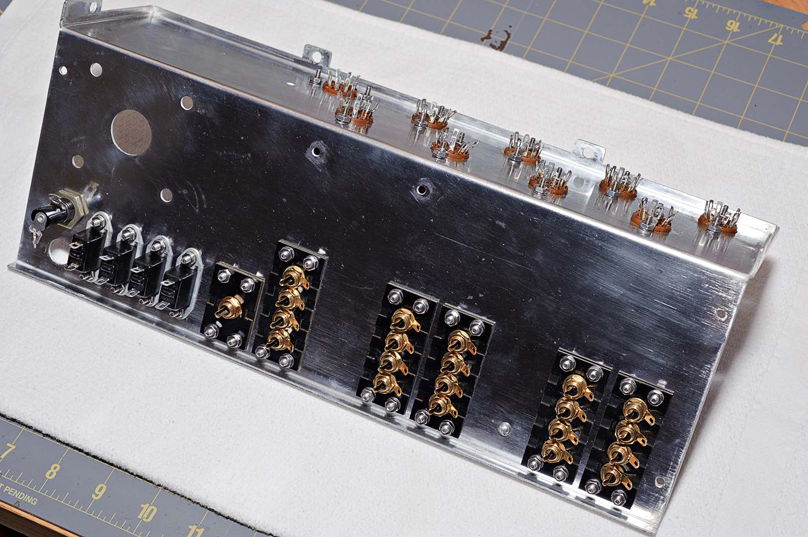
The last phase of the Citation assembly is to attach the power supply assembly to the main chassis and then attach all the wires.  As I've said for the last few posts now, there's not much to it.  Simply follow the instructions in the manual step by step.  The power transformer is attached and the transformer wires are separated into three groups and routed as indicated in the manual.  The bundle of wires from the main chassis is routed through the grommet on the power supply bracket and the bracket is then attached to the chassis using the appropriate washers and nuts.  The following photo shows how the underside of the unit will look after these steps are completed.


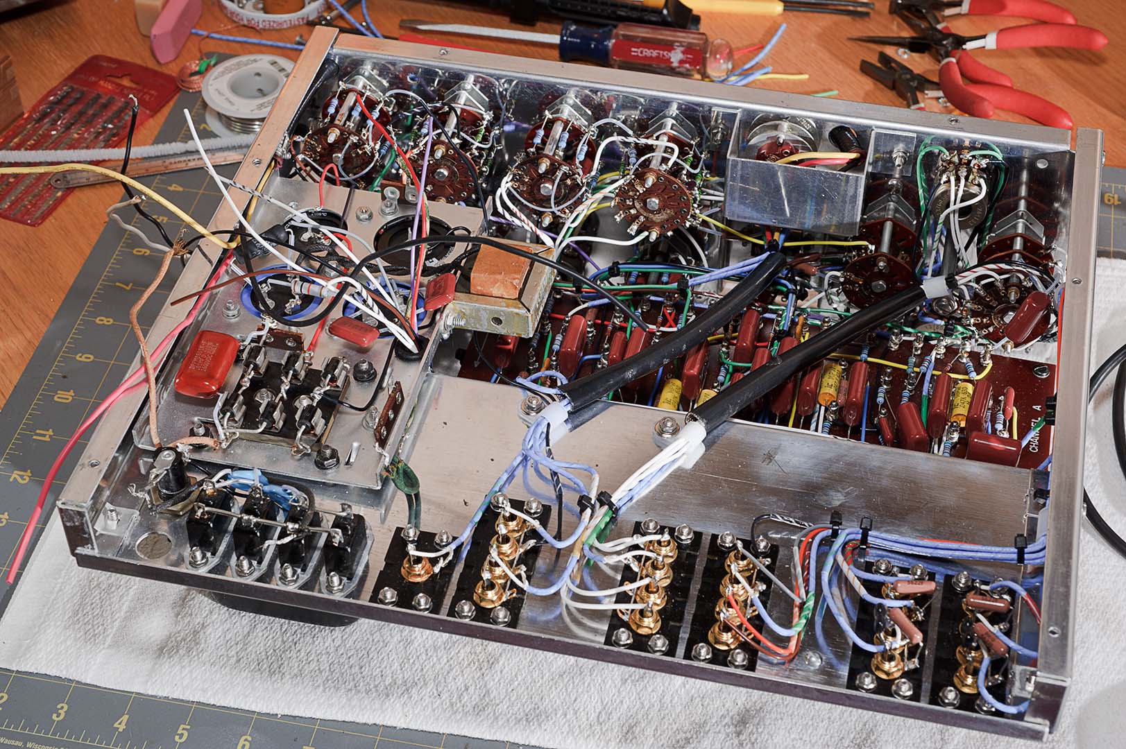
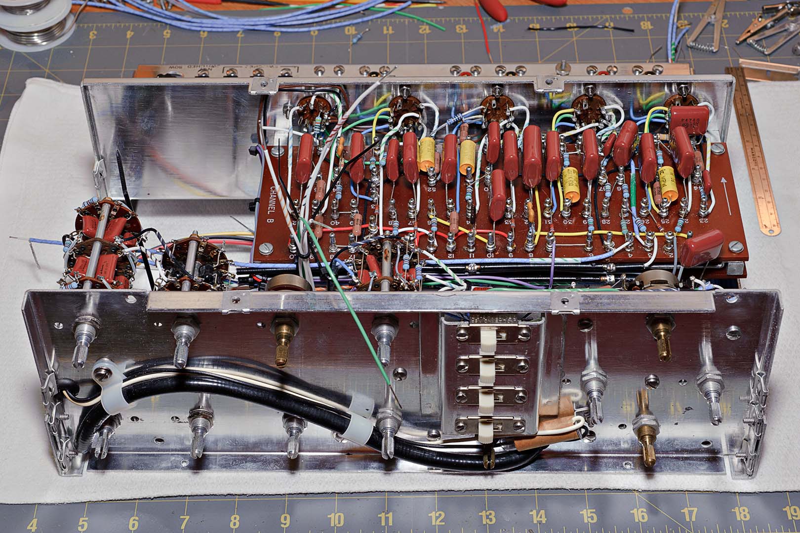
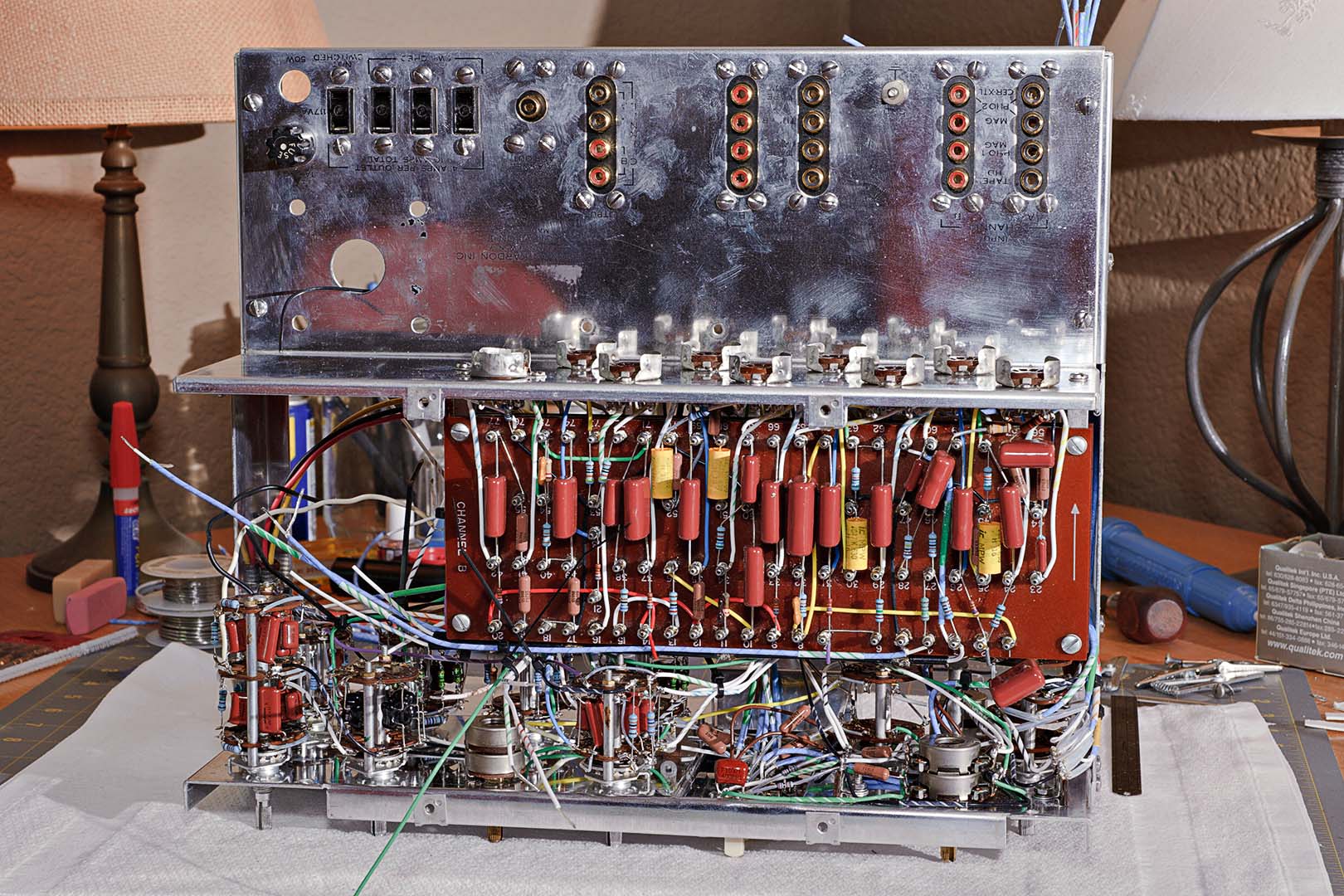
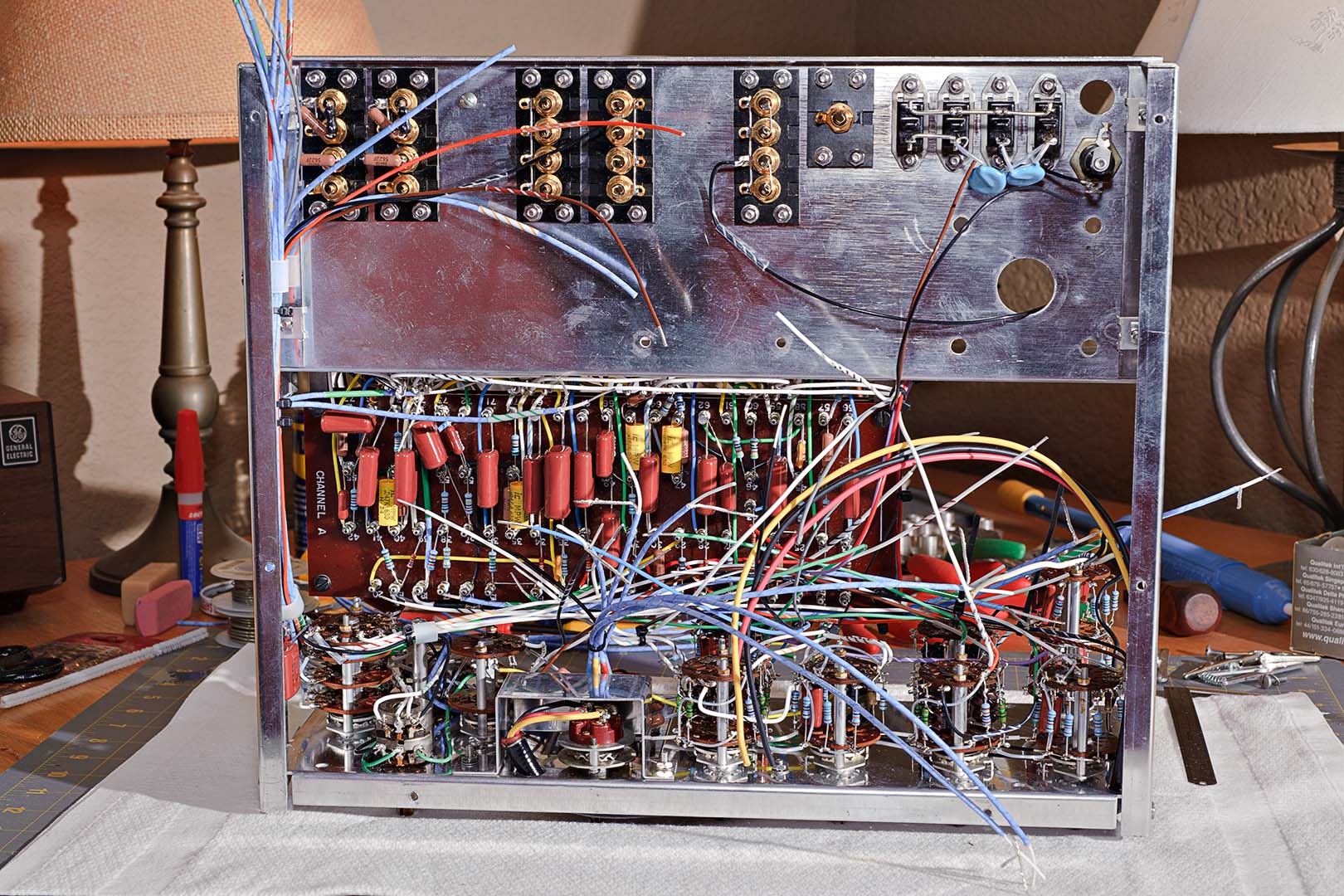
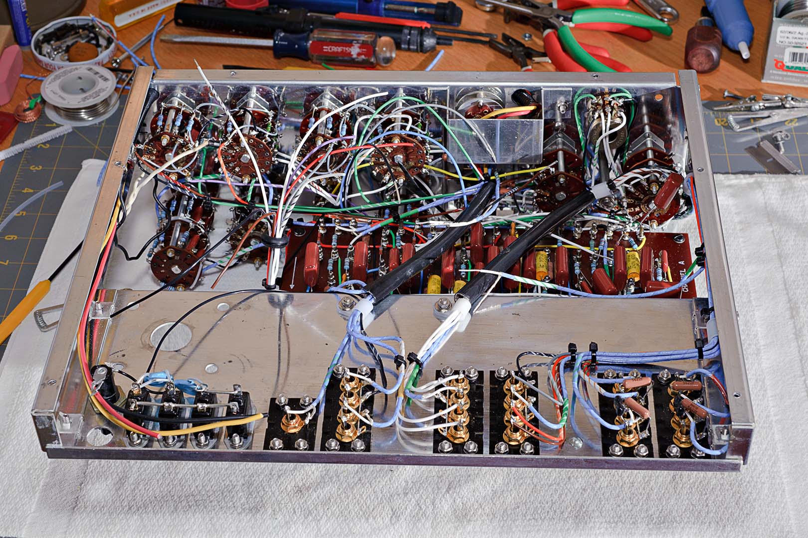
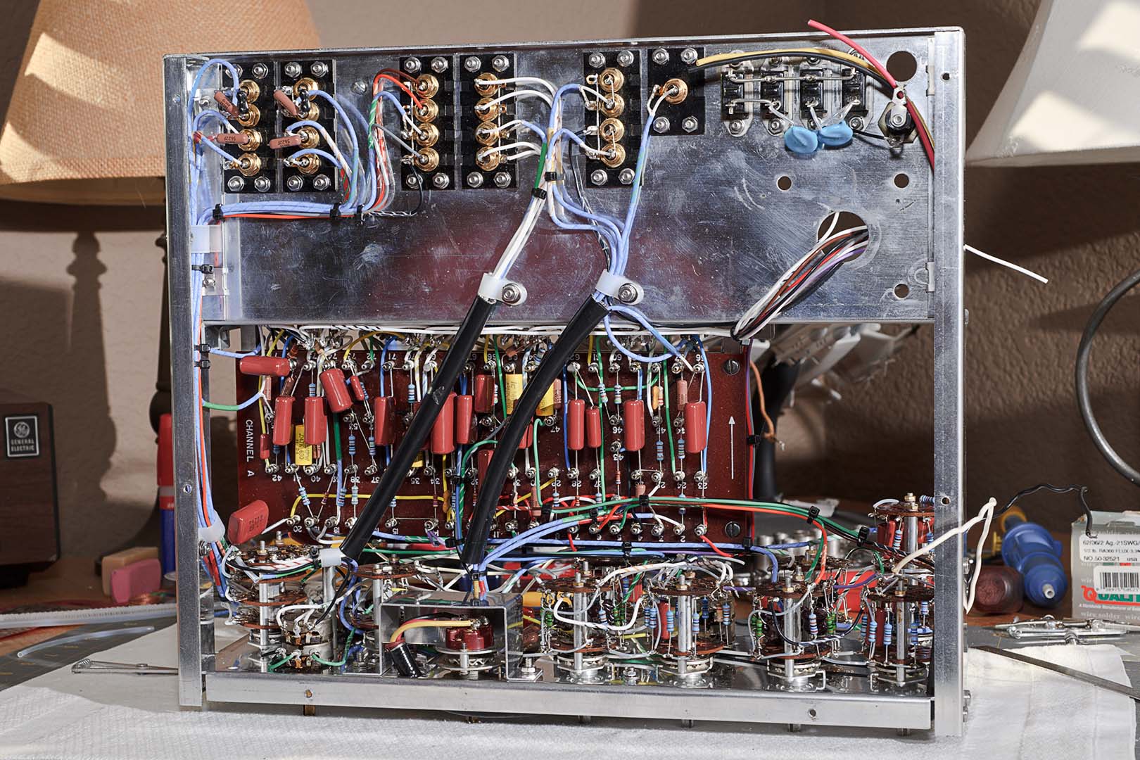
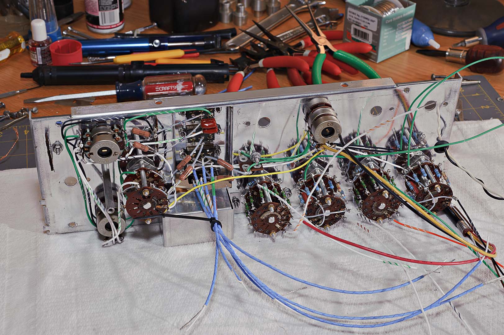
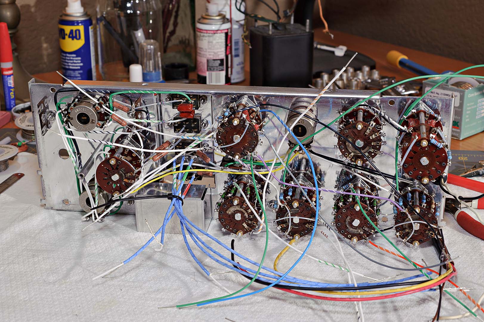
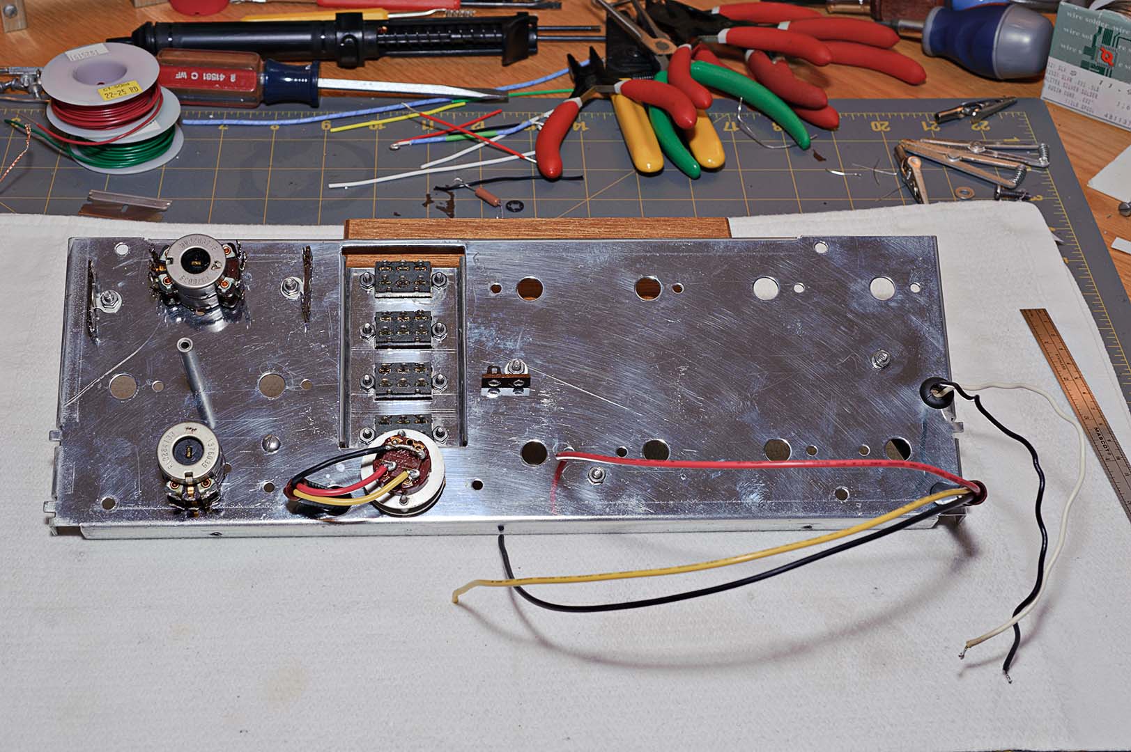
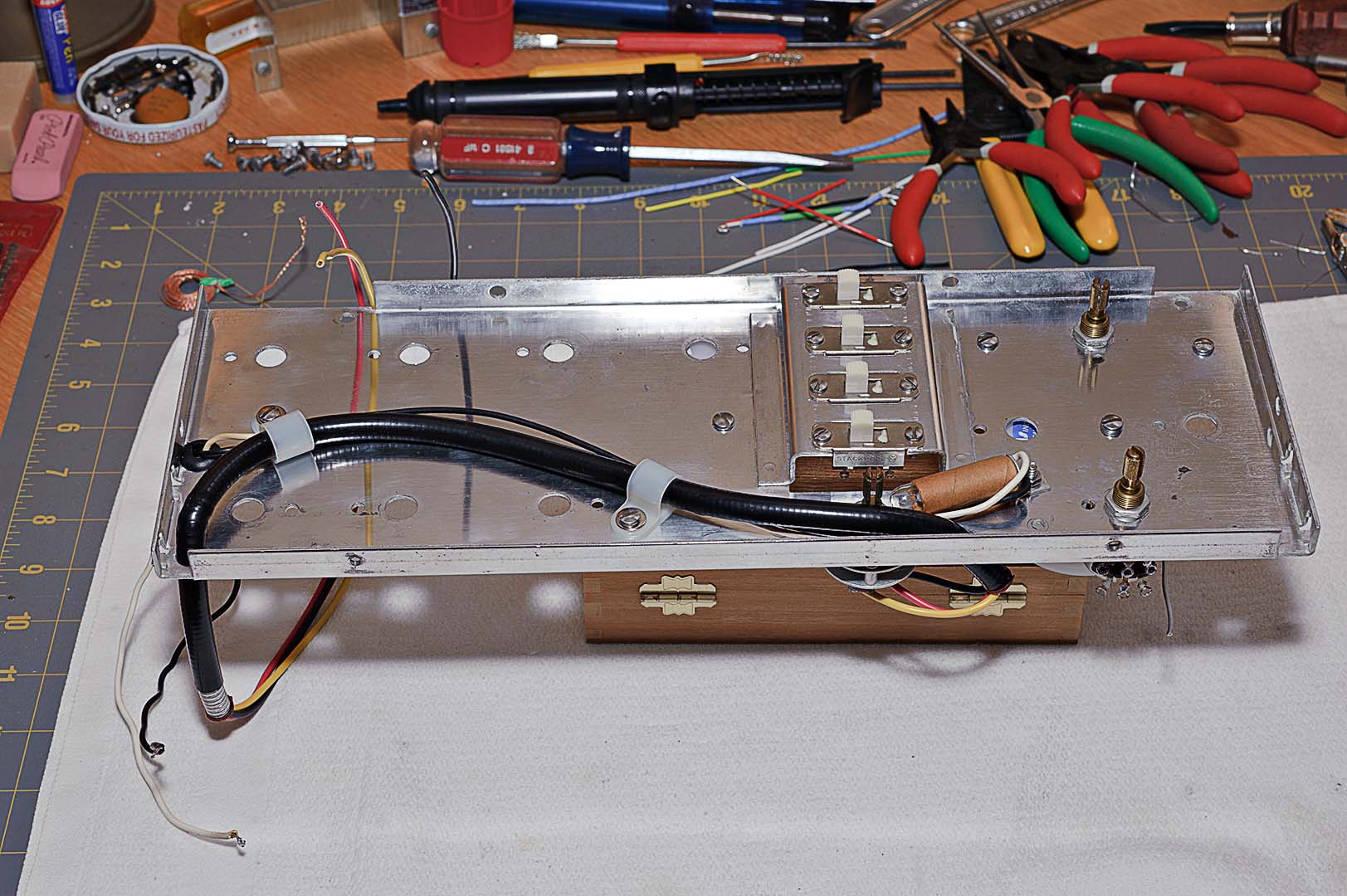
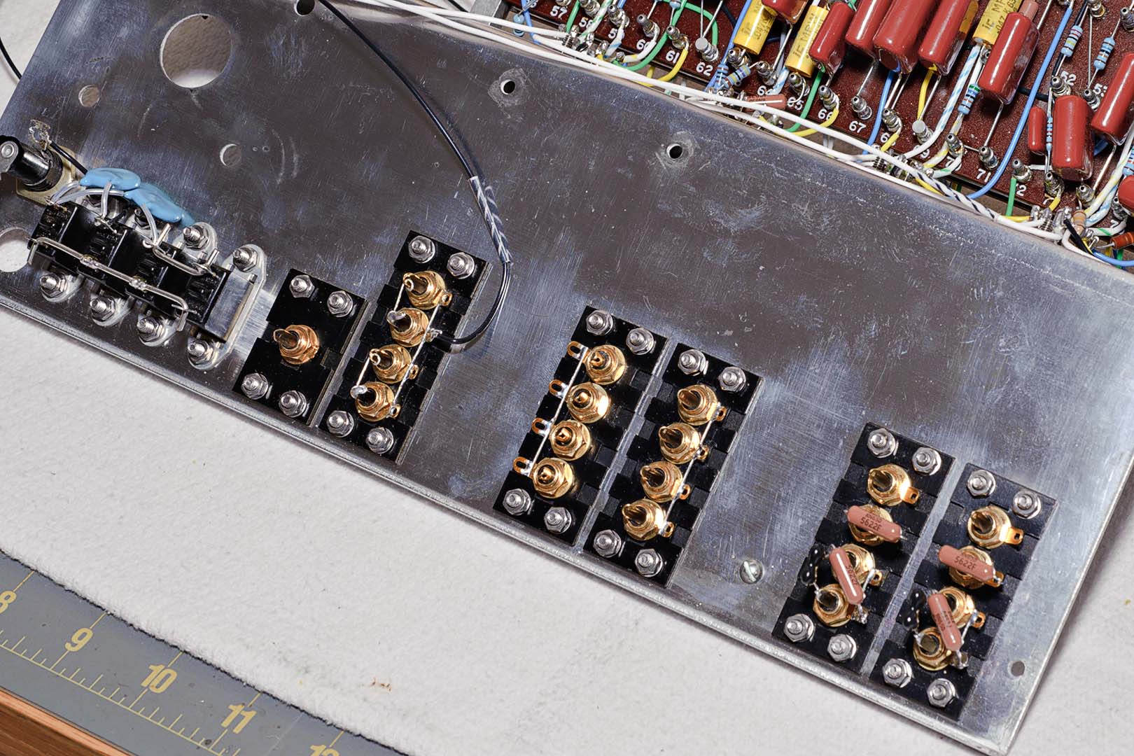
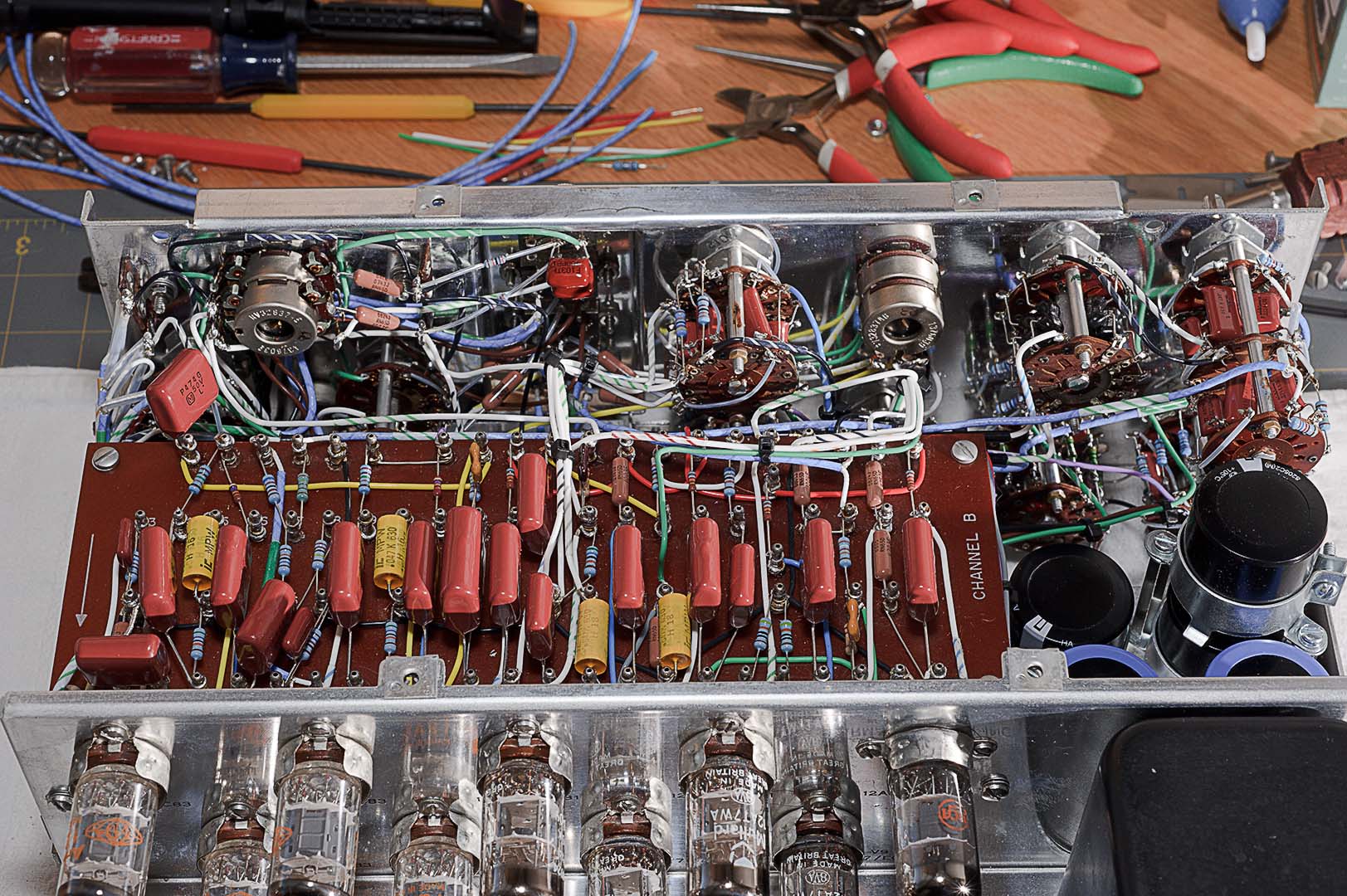
All of the loose wires shown in the above photo now need to be soldered to their attachment points.  Again simply follow the instructions for dressing the wires and solder them to their final destination.  Lastly, the power cord is inserted into the back deck of the chassis and the white and black wires are connected to the indicated points.  That is it for the wiring.  You are done!  The underside around the power supply bracket after all the wiring is complete is shown in the following two photos.  You can see the two capacitors just to the left of the choke (or above, depending on the photo) have been dressed in an upright position as opposed to lying flat as they were before final assembly.  I am satisfied with the neatness of the assembly.


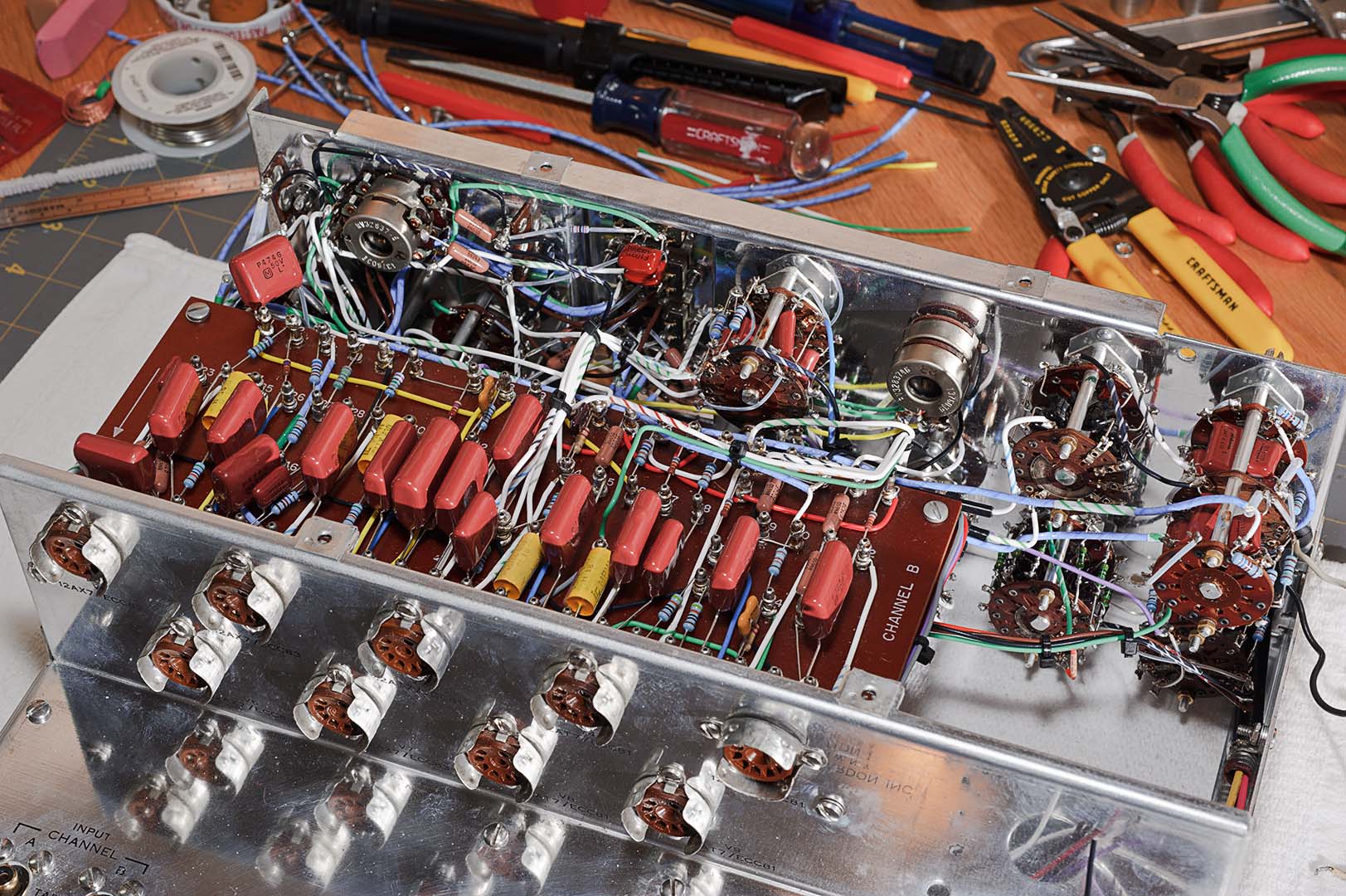
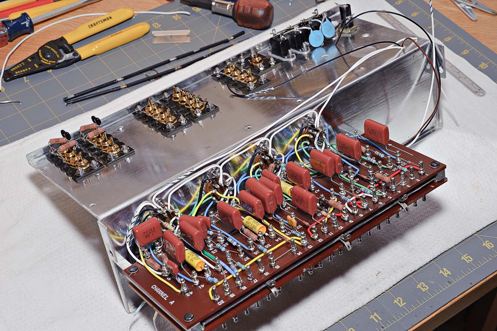
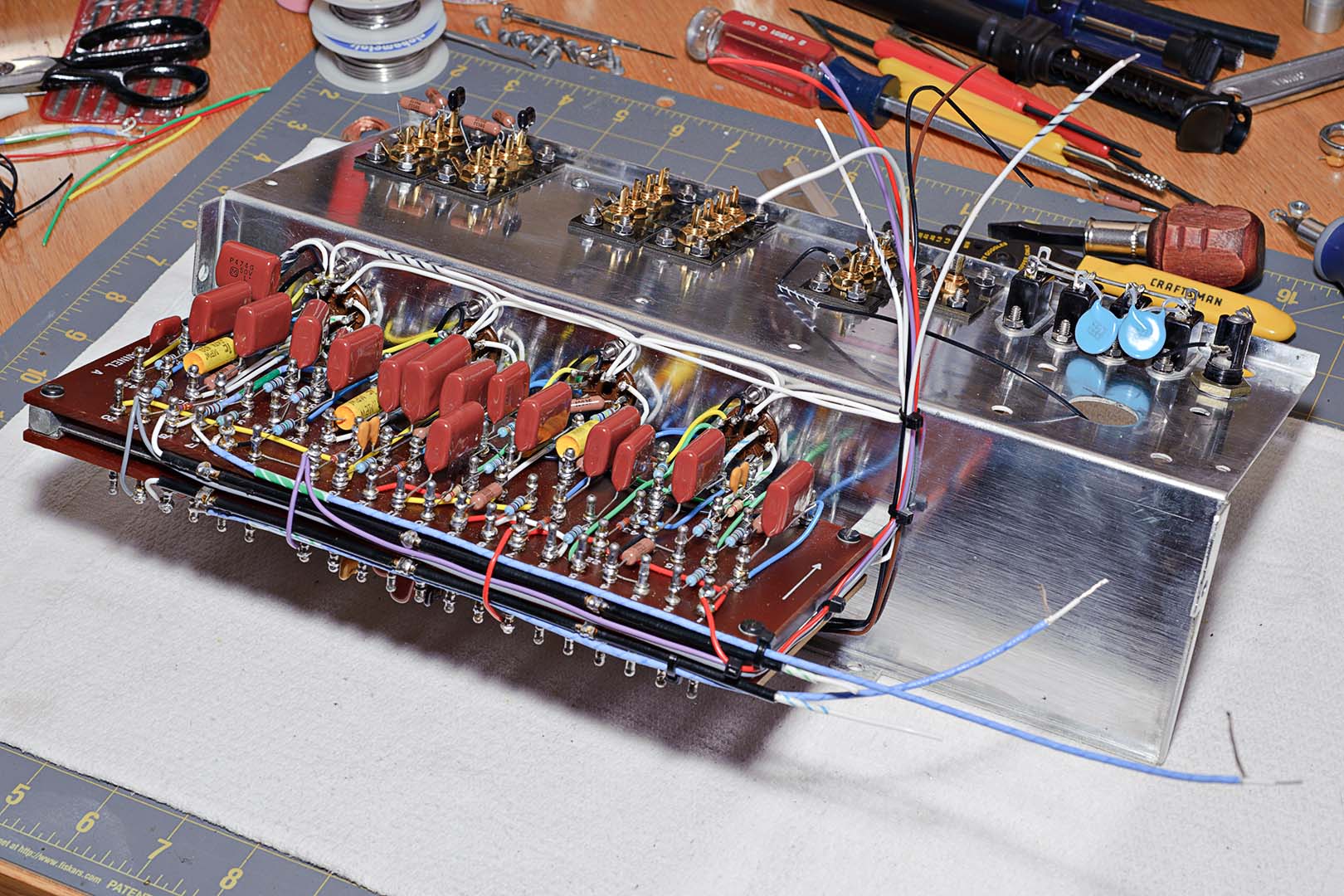
The following two photos simply show the top of the unit after all the wiring is complete.  You can see that I have installed the tubes before I have completed mounting all the final hardware (the front plates, knobs, bottom plate, top cover).  The tubes were installed so that the unit could be tested for correct resistances and voltages as specified in the Citation pictorial diagrams before mounting all the remaining hardware.


The three escutcheon front plates are loosely connected to the back plate.  The hexagonal spacers are attached and all of the plates are tightened.  The clear plastic power switch is installed next.  Finally, the front plate assembly is mounted to the chassis.  It's upside down, but the unit with the front plate installed is shown in the following photo.


Lastly, the knobs are installed onto the switch shafts.  The only thing of note on the knob installation is getting the milled indicator line on the knob pointing to the correct position.  For most of the switches that have discrete settings, like the function switch or the rolloff switch this is a simple matter.  For the loudness and balance pots you'll have to decide for yourself.  I installed my knobs so that they point at 12:00 when the pot is at the midpoint of its travel.  The following two photos show the completed Citation I pre-amp from the front and rear.

The second photo reveals that I have already installed the bottom plate and the rear cover.  In fact, there are a number of things to do before installing these two pieces.  There are a few steps in the assembly manual still to be completed before closing the unit up.  These involve powering the unit on, checking voltages and resistances, etc.

When I first powered my unit on the fuse blew.  Oh no! I thought.  All that work!  I don't know if the added capacitance in the power supply causes a greater initial current draw when the unit is powered on.  In any event, I decided to give it another try with a new fuse.  This time I installed a slo-blow fuse.  This was based on a similar experience I had with my Citation II amplifiers after they were rebuilt with beefier power supplies.  When I powered up this time the unit it stayed on.  Phew!  With the unit on I measured the voltages against the chart.  Everything checked out fine so at this point I can officially declare PROJECT COMPLETE.


The pre-amp was installed inside an original H/K walnut cabinet.  This cabinet has a few scratches and dings that need to be removed with a refinishing project.  However, I have my father's mint condition cabinet in storage just waiting to house a refurbished Citation I.  I will probably save it for when I refurbish my father's unit.  But because I have a blemish free cabinet I don't feel a pressing need to refinish this one at present.

So, what tubes did I install in the completed pre-amp?  I chose to use NOS Amperex tubes for the 12AX7 positions.  NOS Mullard 12AT7WA tubes were used in the line stage positions V3, V4, V8, V9.  These Mullards are the later model military tubes that are usually found boxed as CV4024.  For the V5 position I chose to use a relatively cheap RCA 12AT7 tube.  I was advised not to put an expensive tube in V5 because this tube only serves to light the power lamp and is used for the center channel line out.  If you don't use the center channel, then why waste a good tube?

My final photo for this project is shown below.  This is my system.  Placed on top is a Music Hall MMF-7 turntable on the left alongside the new Citation I.  Down below you can see two Citation II amplifiers.  Both have been completely refurbished using all of Jim McShane's kits and parts.  At present I only have one amplifier in use.  The intention is to use both amplifiers.  I haven't decided yet if I will bi-amp them with my Joseph Audio speakers or wire them as monoblock units.  The shelving unit is from Salamander.


Time Spent: ~4 hours

So ends the project.  I hope there are Citation fans out there who enjoyed reading this blog.  This project was a lot of work, but I enjoyed all of it.  I hope there were things to be learned for everyone who visited.  What's next?  I don't think I'll be doing a second Citation I right away.  I have a couple of Citation II amps that I may work on next.  But, the very next thing on my list is to hook this new pre-amp up to my system and see how it sounds.  I hope you check back from time to time to read my report.

Once again, thanks to everyone for stopping by and reading.  Goodbye for now.

Saturday, August 28, 2010

Citation I Refurb - Final Assembly

So where were we?  Hard to remember, it's been so long.  Embarassing to say that the last post was March 30.  And coincidentally, we left off on page 30 of the assembly manual.  Let's continue.

Speed nuts are installed and the left hand rail is attached.  The flexible metal tubing from the front side of the panel is clamped to the rail and the bare metal portion is soldered to the clamp.  I'm not sure if the soldering is for grounding of the metal tubing in order to shield the wires from eletrical interference or simply to provide a secure attachment.  The front panel and side rail assembly is shown in the following two photos.


The main chassis is attached next.  The main chassis up to this point is comprised of the rear deck (RCA inputs and outputs), the tube sockets, and the A and B terminal boards.  After attachment of the main chassis the unit is seen from the front and top views in the next two photos.  It's really starting to look like it's nearing completion now.


And now a view from underneatch at the Channel A side of the chassis.  Now this looks to be a bit of a mess.  It looks like a plate of spaghetti.  The reason the underside looks so messy compared with the top is that most of the remaining wires that need connection are located on the underside as they run to the RCA jacks on the rear deck.


The remainder of page 31 and the first half of page 32 are a long list of steps to route and connect the wire running to the RCA strips on the rear deck.  There's nothing out of the ordinary to point out here.  Follow each step in the manual and be neat in the bundling and routing of the wires.  New plastic nylon clamps were used to secure the main wire bundles running to the rear deck.  Harman Kardon did a good job in the instructions of laying out a neat chassis.  Following their steps and using small cable ties in place of the original black tape should result in a tidy appearance.


The second half of page 32 and all of page 33 deal with connecting the remaining front panel switch wires to their proper terminations on the terminal boards.  Again, there's nothing complicated or noteworthy here.  As commented on above, simply follow the instructions step by step.  If there's is any advice to give out it would simply be to repeat the neatness theme.  If you work carefully, following the instructions, you almost can't help but be neat.  The following two pictures show what the underside of the chassis looks like after the wiring of terminal board A is complete. 


Once the underside and terminal board A are complete the chassis is flipped over and wiring of terminal board B is completed.  The completed topside is shown below.  In the two photos above and the one below you can no doubt see the striped labels that were wrapped around many of the wires.  You may have to click on the image to zoom in.  The use of laser labels for creating "striped insulation" wires seems to have worked out well.  The proof of how well it worked won't come for a couple of years.  When the chassis is opened up in 3 or 4 years' time will the labels still be wrapped snugly around the wires.  I'm actually betting that they will be.


That completes the wiring of the switches and the terminal boards.  We're almost finished.  The remaining work is to install the power supply section that was completed a long time ago.  And after that is the final assembly of the enclosure and knobs.

Total Time:  ~12 hours

Tuesday, March 30, 2010

Citation I Refurb - Front Panel Continued

There is no lead-in to this blog post.  We are simply going to continue work on the front panel, picking up in the middle of page 28 in the assembly manual.  The mode switch is installed first.  The wires on the wafer are connected to the balance control and one of the terminal strips.  The pair of 47K ohm resistors from the mode control are connected to one of the slide switches.

At this point allow me to make a comment.  The instructions on this page of the manual make a statement to "Make certain that the wires from these resistors do not touch each other or any of the other pins on the switch."  I ensured this by slipping on lengths of Teflon tubing to these and all resistors and capacitors installed inside the chassis that have appreciable length leads.  You will see this in the photos which follow.

The blend control was installed next.  After locking in place several wires and a 220K ohm resistor are connected from the blend control to various points on the front panel.  The photo below shows the state of the front panel at this point.  It is worth noting at this point that the panel is still relatively bare.


The next switches to be installed are the treble and bass switches, S4 through S7.  The aluminum cover for the power switch is also installed at this time.  With each switch that is installed the panel becomes more cluttered with wires that will not be attached to their destinations until later.  The photo below shows the work at this point.


The turnover and rolloff switches are installed next and wired together.  This is followed by the installation of the low-cut switch.  Wires from the switch are connected to the bass switches.  The photo below shows the state of the front panel at this point.  Note how cluttered the panel now is before the wires are organized.


The next steps of the instructions call for taping together groups of these wires that will be routed to similar destinations on the two terminal boards. Of course, I will be using cable ties instead of tape.

Next comes the installation of the last switch, the function switch.  This is the switch that I referred to earlier as a medusa's head.  After the switch is installed the various wires, mainly the shields from the shielded wires, are connected to the proper destination points on the chassis as indicated in the manual.  The twisted shields are all covered with lengths of Teflon tubing for insulation from each other.

At this point I found that a couple of the twisted shields, even after careful measuring, simply did not reach their destination on the terminal strip comfortably.  I also found that even with insulation tubing placed over the shield wires there still seemed to be a danger that the wires could possibly touch each other.  I stopped my work at this point to think through what to do.  In the end I picked out a couple of wires that seemed to be the biggest offenders and simply removed them and replaced them with wires of slightly different lengths.

The next step is to group and tape together the wires from the function switch.  The wires are grouped as indicated in one of the supplied pictorial diagrams.  Because I used cable ties in place of tape I did not fully bind the wires.  Instead, I left a bit of slack in the cable ties so that I would be able to adjust the ties later, after the wires had been routed to their destinations inside the chassis.

Finally, the right side rail (on the side next to the function switch) is attached.  At this point the front panel looks like the following photo.  There's a lot of wires there.  Think what it would look like if the loose wires weren't cabled together in neat bundles.


I'm now one-quarter down on page 30.  The final steps of the front panel wiring are to neatly rout the wires from the function switch.  The manual is very clear in pointing out how important it is to dress the wires properly so that a neat and professional appearance is obtained.  This includes making sure to dress the wires in each bundle all parallel to each other, no crossing of wires.  This makes for a neat appearance as well as keeping the bundle diameter to a minimum.

That is the only comment I can make at this point.  The rest of the work is simply following the instructions as outlined in the assembly manual.  New plastic cable clamps were used where specified in the instructions.  When you reach the end of page 30 the front panel work has been completed.  The result is shown in the following photo.  Don't be confused by the extra shielded wires on the left to the rear of the panel (lying on the desk).  These are extra shielded wire lengths for the next stage of construction and are not connected to the front panel.


That completes the front panel installation.  As in my previous blog post I forget how long the front panel took to complete.  I'll take a guess though.

Total Time Spent:  ~8 hours

Saturday, March 27, 2010

Citation I Refurb - Wiring the Front Panel

I'm back.  Finally, after over 4 months.  I'll be honest and admit that I'm actually further along on this project than the blog posts would indicate.  With holidays and travel the blog just got pushed way down on the priority list.  I don't want to leave this project unfinished, however, so let me complete the rest of the write-up.  So where were we?

Way back on Nov. 21 I had just completed the switch wiring and was now ready to begin on the front panel, which is described at the bottom of page 26 of the assembly manual.  I think I made mention in the last post that all of the hard work has been completed and the remainder of the step are pretty straight forward.  This is mostly true.

The four slide switches were installed in the front panel followed by a new small rubber grommet.  The AC switch was installed and a new #1815 pilot bulb was installed, even though the old one was still working.  The pilot lamp assembly was mounted onto the panel and the wires routed through the new grommet.

The wires that run to the power switch were prepared next.  This is the one place in the project that I did not use Teflon coated wire.  Basically, I just couldn't find any wire of sufficient gauge that I could buy in small quantities.  I ended up buying 25ft spools of 16 gauge PVC coated wire (80°C, 300V).  I also could not find the original colors of blue, tan, and black.  Instead, I had to settle for black, yellow, and red.  Yellow replaced tan and red replaced blue.  The wires were run through the original insulated metal tubing, mounted to the chassis using new plastic clamps, and soldered to the power switch.

The lug strips (TS4, TS5, and TS6) were installed. Finally the tubular spacer was attached and the loudness and balance controls were mounted. The end result at this stage are the two photos below, one from each side of the panel.


The next steps in the manual cover the wiring of the loudness and balance controls as well as the preliminary wiring of the slide switches.  In the photo below you can see more examples of the labels that I used to indicate the striped wiring.  You can also see that there is also a fair amount of shielded wiring that runs from the slide switches, specifically S13 and S14 (stereo reverse and phasing switches).


At this point I am going to stop.  My bookmark is on the middle of page 28 of the assembly manual.  With any luck I can complete this assembly in just a couple more blog posts.  I would like to be able to say how much time the above work took to complete.  Unfortunately, it was four months ago and I just don't remember.  I'll give an estimate anyway.

Time Spent:  ~2-3 hours

Saturday, November 21, 2009

Citation I Refurb - Wiring the Switches, Continued

In the previous post I went through the pre-wiring of the switches as they come from the factory.  I didn't mention that the drawings that I have created for the switches will be posted in The Citation Sound forum on Yahoo.  They're not there yet and, in fact, I haven't yet completed all the drawings using OpenOffice Draw.  But they will find their way there at some point.

And one last item about the drawings.  In reading ahead in the assembly manual I found that a tiny bit of the wiring that I did is actually outlined in the assembly manual.  This is not a big deal.  But if anyone happens to use my drawings in the future to rewire a Citation don't be confused when you return to the manual and find some wires specified in the instructions already attached to the switches.

With the factory wiring out of the way I can now return to the Assembly Manual.  I left off towards the top of page 23 so let's pick it up from there.  Things are going to be pretty straightforward from here.

Page 23 outlines the steps for wiring the bass, treble, rolloff, and low cut switches.  There really isn't much additional commentary I can make.  These switches are the easiest to wire and consist mainly of attaching a few variously colored wires.  There is a lot of striped wire used for these switches, which I labeled using the method I have described previously.

The only decision I had to make was whether to use one or two labels for the striped wiring.  Some of the switch wires end up attaching to the terminal boards and others attach to other switches.  In general, if a wire went to one of the terminal boards I used two labels, one at each end.  This made sense as these are usually longer wires.  The wires that attach to other switches are usually short and a single label wrapped around the middle of the wire will suffice.

The striped wires that run from a switch to the terminal board present another unique problem.  To keep the inside wiring neat the wires from all the switches are collected into a number of bundles.  These bundles are then tied together and routed neatly around the chassis.  It will be next to impossible to neatly bend a teflon coated wire at the point where a label is attached.  This means I have to take extra care in where I attach the labels.

I solved this problem in two ways.  First, I only attached the switch end label at this time.  I will attach the second label later when I am tying the wires together and routing the bundles to the terminal boards.  Second, I have the luxury of having another Citation I available.  This allows me to look at where a wire is going to route immediately as it travels away from the switch lug.  Based on this I can locate the first label in a good spot that will minimally interfere with any wire bends.  If you don't have a second Citation unit for reference you'll have to look at Citation I pictorial drawings.

The wiring of the mode switch is described on page 24 and is the next step up in complexity.  There are bare wires, insulated wires, and a couple of 47K resistors that need to be attached.  Still all relatively simply.

On the bottom of page 24 begins the function switch wiring.  This one is a beast and the instructions for this one switch cover two full pages of the manual.  This switch not only has many more wires than any of the other switches, but at least half of those wires are shielded wires.  I only have one picture to accompany today's post and this is it.


This picture represents the preparation of shielded wire.  Pictured are a short ruler for measuring the end for stripping, a wire cutter/stripper, a razor blade, a pointed pick (that came with a soldering kit) to "unbraid" the braided shield, a coil of shielded wire, and shielded wire samples in various stages of preparation.  Note that the wire pictured is what I described in an earlier post.  It is single conductor 22 gauge stranded silver coated wire with a Teflon jacket.  It is then wrapped with a braided silver coated wire shield and covered with a Teflon tape jacket.  This wire was purchased from a vendor on eBay.

An appropriate length of wire is measured (with a longer ruler not pictured) and cut.  Using the short ruler I follow the instructions in the Citation manual for how much outer insulation to strip away.  I use the razor blade to cut through just the insulation, being very careful not to nick the braided shield.  I found that in addition to cutting a "belt" around the wire I also had to cut a slit the length of the wire in order to remove the insulation.  I first tried to strip the outer insulation using the wire strippers.  This didn't work as the stripper either didn't cut all the way through the insulation or it cut some of the wires in the shield.

I then use the pick to unbraid the shield wires.  When the shield is unbraided back to the outer Teflon jacket the individual shield strands are carefully pulled together, straightened as best as possible, and then twisted tightly.  This is a time consuming task.  It doesn't take all that long to unbraid a single wire end.  But when you have to unbraid each end of the wire and you then multiply that by all the shielded wire used in the assembly of the Citation I you will find that a lot of time is spent simply unbraiding the shield.

A measured length of the inner Teflon jacket is then stripped away.  Both wires, the shield and the inner conductor, are lightly tinned.  Lastly, a colored label is attached to an appropriate location near the end of the wire (as seen in the picture).  Note that when using shielded wire you even have to use labels for solid colored wires, not just the striped wires.

The wiring of the function switch is not particularly complicated.  It's simply messy.  There are a ton of wires to attach and it quickly gets very crowded.  Clear Teflon spaghetti tubing of the appropriate diameter is used to insulate the exposed shield wire in place of the original Citation kit black insulation.

I wish I had taken a photo of the completed function switch to give an idea of how unwieldy it is.  Of course, cable ties will be used to gather the wires together in bundles for neat routing around the chassis.  But until then you have a Medusa's head on your hands.

That completes the rotary switch wiring.  Next time I'll pick up with the wiring of the front panel.

Total Time Spent:  ~8 hours

Saturday, November 14, 2009

Citation I Refurb - Wiring the Switches

It seems there has been another gap in my posts.  I'm not sure what has come up over the last two weeks that has kept me from this project, but here we are two weeks later.  What's next?  Well, according to the assembly manual it's time to pre-wire the switches.

Perhaps Harman Kardon should have called this "completion of the pre-wiring".  In fact, the H/K factory has already performed pre-wiring of the switches.  Almost all of the switches come with resistors and capacitors already soldered to their appropriate switch locations.  The Function and Mode switches are the two that do not come prewired.  What the manual calls "pre-wiring" is simply attaching lengths of wire to the switches before mounting the switches to the chassis.  It would be difficult to mount the switches first and add the wiring afterwards.

But remember, my project is a complete replacement of all components.  This means that I am going to desolder every resistor and capacitor (and wire) from each switch and rewire it with new components.  Here's a photo of two switches, a treble switch and the rollover switch, with their original components attached.


Ok, let's start desoldering and get this project moving again!  Whoa, whoa, whoa... slow down!  Just how am I going to rewire these switches?  They all came pre-wired from the factory.  There are no pictorials from Harman Kardon that I am aware of that show how to wire one of these switches.  Solution?

You guessed it.  I'm going to have to draw up a diagram for each of these switches before I tear it apart.  And I had better take my time and check, and re-check, my drawings.  Fortunately, I have other Citation I units that I can open up and use as references, even after I've removed all the components from the switches.  So, first step is to get a pencil, an eraser, and blank paper.  Let's start drawing.

Creating the drawings was a long task.  It's not particularly hard.  You just have to go at it slow.  I had to make liberal use of the eraser.  It's not really so much because of any carelessness on my part.  Keeping the switch oriented properly as you transcribe component locations from the switch to paper, counting out the switch lugs properly, etc all contribute to mistakes on paper.  At the start I had to decide how best to depict the wafers and the orientation of the switch.  I finally decided to draw wafer #1 (the wafer nearest the chassis, or what I called the front wafer) as a large circle and I then drew wafer #2 (the rear) as a smaller circle inside of wafer #1.  To keep orientation the same in all the drawings I decided on a standard of placing the locking tab on the right side of the drawing with the shaft pointing away from you.  Here's an example of my drawings, in this case the low-cut switch.


After I had all the hand drawings completed I decided that I wanted a little more for permanent documentation purposes.  So my next task was to convert all of these hand drawings to some sort of computer file.  I wanted something that looked similar to the H/K supplied pictorials.  I would have prefered to use MS Visio, but I don't have that program at home.  Instead, I chose to install the Open Office suite (OpenOffice.org) and created all the drawings in OpenOffice Draw.  To keep the drawings from becoming too cluttered I broke the drawings apart into multiple views.  For example, the Low-Cut switch above was broken apart into three views; the wires alone, the top half of the switch, and the bottom half of the switch.  Here's what the finalized pictorials look like.


Now that the drawings are all complete all that needs to be done is to remove all the components from all switches and solder in the new components.  Yeah, that's all.  In actual practice it takes a lot longer than it just took me to type that sentence.  Drawing up a single switch, double checking it, removing all the old components, cleaning up all the switch contacts with DeoxIT, and soldering in the new components was an entire evenings work for a single switch.  And that doesn't count the time spent on the OpenOffice drawings (I did the OpenOffice drawings after I had completed all the switches.).  There are a total of 9 rotary switches that need to be taken apart and cleaned.  However, only 7 of those switches need to be rewired at this point.  The Function and Mode switches do not contain any resistors or capacitors installed from the factory.

When adding the wiring I did not use color insulated wiring for wires that went from one switch lug to another.  Instead, I used bare wire.  If a wire was long enough or was located in a position where it might touch exposed metal I used teflon tubing as insulation.  Here's a photo of the completed Rolloff switch.  There is no insulated wire on this switch but you can see the bare wire used to connect various lugs.


The treble switches were the most fun to work on.  For some dumb reason I enjoyed assembling the paralleled capacitor-resistor configurations.  As you can see in the following drawing I used the same technique as employed by Harman Kardon in the factory.  This photo shows my own construction alongside the original components that I removed from the switch.


I think that just about covers the work done on the rotary switches.  For the potentiometers I didn't do a lot of work.  The only thing I did was to apply some DeoxIT to the pot and rotate the pot back and forth a number of times.  The four slide switches were handled similarly.  I used rubbing alcohol to clean all the finger grease and dirt off the white finger slide and used DeoxIT on the actual backside slide switch.  I was pleased with how well the front side of the switch, the cosmetic side, cleaned up.  They now look almost brand new.

Here are all the completed front panel switches laid out in their approximate front panel locations.  Taken as a whole, this has been the most time consuming piece of the whole reconstruction project.  With each rotary switch taking 3 or 4 hours to complete it was approximately a two week long process to finish up all the front panel switches.  But I can honestly say I am very, very pleased with the results.


Total Time Spent: ~40-50 hours

Tuesday, October 27, 2009

Citation I Refurb - Chassis Wiring Continued

Yesterday's post left off at the top of page 19.  Let's pick it up from there, which begins with the wiring of the phono sockets, newly upgraded to gold plate.

But first, let's pause here and go back two posts to a question I posed then.  Does it matter which side you position the ground lugs on when assembling the new phono strips?  Like a lot of things in life the answer is "it depends".  If you use RCA phono sockets that all have the same color insert then the answer is "No".  If you really don't care how neat your wiring job is the answer is also "no".  However, if you're using color keyed phono socket inserts like I am and you care about neatness then the answer is "Yes".  Here's a photo repeated from yesterday's post showing the chassis after the mounting of the RCA strips.


See how I have mounted the strips with the grounding lugs all pointed the same way?  This is wrong!  Unfortunately, I didn't catch my error in time.  I proceeded as indicated in the manual and completed the wiring of phono sockets.  When finished I looked at my work and then thought about how all the other wires that connected to the phono sockets were going to be arranged (or "dressed" as seems to be the proper term) in later stages of assembly.

See the two wide sections of bare chassis that run between the parallel strips of phono sockets.  Those bare areas are where you want to run the wires to the sockets.  So what you really want is to mount the phono strips such that the ground lugs are located next to the open chassis areas.  If you do like I did in the upper photo the wires will have to be dressed over the top of the sockets to reach the ground lugs.  Now look at the following photo.


This is the arrangement that I ended up with.  See how I flipped around one of the strips, the fourth strip from the right?  I couldn't do that with the second strip from the right because 1) it was already wired and 2) this is one of the strips where I filed down the retaining washers so the grounds wouldn't touch.  Even if I desoldered the components I would still have had to remove the individual sockets themselves and remount them.  After the finger torture I went through to assemble them in the first place I was not about to disassemble and reassemble them again.  Similary, the last strip of four on the left cannot be flipped around either.  This strip has two red and two black inserts.  Flipping the strip around will make the red inserts the A channel and black will be B.

I corrected the orientation of the one strip I could change and left it at that.  If this is the worst mistake I make in the assembly of the unit I will have done an alright job.  But this does make a point.  Think out your work carefully.  And if you are using replacement parts with different geometrys than the originals then think ahead to issues that may arise.

The rest of the steps on page 19 were completed in sequence.  One item of note is the substitution of the original dual section triple lead 0.01 μF, 1400V capacitor.  From on-line discussions with members of The Citation Sound forum, particularly Paul Wolfe, I learned that this was a "safety" capacitor.  Except that it really isn't a true safety capacitor.  I replaced the stock cap with two X1/Y1 0.01 μF safety capacitors from JustRadios.com.  This safety cap has been tested to withstand 2500V AC for one minute.  Convenience outlet CO4 was used as the common tie point.  JustRadios.com has a good article on safety capacitors, the different types, and their uses.  Highly recommended reading for those restoring old vintage equipment.

The last step on page 19 is the attachment of the terminal board assembly to the chassis.  The terminal board assembly is described on page 16 of the manual.  If you recall from a couple posts back I did not assemble the terminal boards at that time due to the fact that I saw no way to store the assembly without bending some of the wired components.  So back to page 16 to complete the terminal board shield assembly and then back to page 19 to attach it to the chassis.

With the terminal board assembly now attached to the chassis the next steps are to connect all the wires from the terminal boards to the tube sockets.  The steps for this are laid out on pages 20 and 21, and a bit on page 22.  There are a lot of steps on these two pages, but not really much to comment on.  Well, I do actually have a couple comments at this point.

The first is that if you choose to use 20 gauge stranded wiring like I did you will have to be very careful when attaching the wires.  As I've already described way, way back I found this wire hard to work with for delicate wiring situations like the tube sockets.  Once you tin the ends, and you must do this, the wire becomes very stiff.  On top of that the pin lugs do not have very large holes.  For those pins that have multiple wires attached the size of the wire makes it a very tight squeeze.  But I took care and completed this wiring stage without incident.

My second comment is a general one regarding exposure of bare wire.  Whenever possible I am using clear Teflon tubing as sleeving to cover lengths of exposed wire.  For example, in the wiring of the tube sockets there are resistors running between the board and the sockets.  I use Teflon sleeving to insulate the longer resistor leads.  Likewise, I used Teflon to cover the leads of the X1/Y1 safety caps described previously.  The one big exception is that I did not use any sleeving on the components mounted entirely on the terminal boards.

After completion of the tube socket wiring I was left with the chassis as depicted in the photo below.


Let's power through one more page of assembly instructions before ending this post.  Continuing with the steps on page 22 I now attached the black flexible metal tubing to the edge of the terminal boards.  You can see the black tubing lengths sitting on the desk above the chassis in the previous photo.

Shielded wire was prepared, attached to, and then run along the terminal board.  Next, long lengths of purple, gray, and red wire were attached and dressed along the outside of the boards.  These wires were then dressed together with the black, white, white/black, and brown wires from the early tube socket wiring described in yesterday's post.  I'll make a note here that I am not using black tape to neatly bundle wires in my project.  Instead, keeping up with modern technology, small black cable ties are being used whenever black tape is called out in the instructions.

Short lengths of the same purple, gray, and red colors were used to connect lugs between the A and B boards.  Long lengths of wire were then prepped and run through the flexible black tubing.

That's it.  I'm now on the top of page 23 and will stop for the night.  The next section of the manual is to tackle the switch wiring.  We're going to have to take another detour here from the instructions, but more on that in the next post.

As I end this posting, let's take a look at the work to this point.  Here's a photo.  It's beginning to look very nice, I think!


Total Time Spent:  ~5 hours.