Tuesday, September 29, 2009

Citation I Refurb - Repairing Terminal Board A

If you recall from a previous entry I discovered two terminal lugs on Board A were broken, snapped at the base.  These were lugs #62 and #69.  My first attempt to fix this was aimed at trying to preserve the original look of the board by reattaching the broken lugs.

I was reasonably successful in reattaching the broken lugs to the terminal board.  This was accomplished by using a length of bare #22 gauge wire.  I crimped one end of the wire back onto itself a couple of times.  This formed a small "ball".  The wire was passed up through the bottom of the terminal board.  If the ball is large enough you cannot pull the wire all the way through as the ball stops it at the terminal board.  The wire is then threaded through the terminal lug and out the top hole of the lug.  The lug is seated tightly against the terminal board and the wire extending out the top of the lug is bent tightly over the top and clipped off, leaving a couple of millimeters to anchor the lug.  Solder is then run into the lug from both the top and bottom.

This results in a very good looking repair.  When finished the lug looks original and it feels rock solid.  So I fixed both lugs this way and proceeded with the assembly of the terminal board.  As you may guess by now, this repair may look sound but it doesn't really work well.  As soon as you solder components to the lug, the solder inside the lug melts and the lug comes loose from the terminal board again.  You can get around this problem by simply holding the lug firmly in place with a needle-nose pliers after soldering the components to the lug.  Heat up the lug to melt the solder while holding the lug in place with the pliers.  Keep the lug firmly in place while it cools and the solder solidifies.  This works, but it just doesn't seem like a quality repair to me.

So on to option #2.  A search of the internet parts stores turned up a store called Angela Instruments.  This place seems to specialize in parts for the repair of vintage guitar amplifiers like Fender, etc.  They had kits to assemble entire turret boards.  Well, I didn't need a whole turret board, just a couple of lugs.  But this opened the door to a better search of the internet now that I knew what I was looking for.

I found what I was looking for from a company called Keystone Electronics Corp (http://www.keyelco.com/).  They sell a variety of terminal lugs and the necessary tools to mount them to boards.  The lugs that came closest to what I was looking for were 0.172 double turrets.  The exact variation to mount in the Citation board was Part #1503-4.  In order to mount these in the board I needed what is called a staking kit.  I didn't want to invest a lot here for what would be used for a couple of turrets.  I found what I needed in Staking Tool Part#TL-8.  This consists of a small anvil and a top setting tool (or swager).  I ordered these parts from Mouser.  The staking kit was $17.25 and the termial lugs were $0.41 per lug.

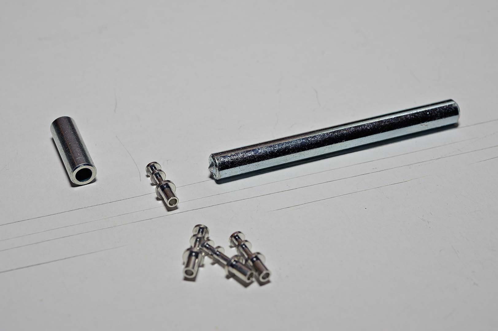
The parts are shown in the following photo.


Before you can install the new lugs you need to remove the vestigial traces of the old lugs.  The lugs were broken off at the top of the terminal board leaving a metal portion of the lug embedded in the board.  This must be removed first.  I use a combination of Dremel tool with a filing bit and a regular power drill with a regular drill bit.  You have to proceed very carefully when removing the lug traces.  Do not simply apply a power drill and bit to the socket and press the power button.  Through a process of slow and deliberate work the remaining lug stub can be extracted.

The bottom of the lug (the mounting portion) is inserted through the hole in the terminal board from the top.  Just a tiny length extends out the bottom side of the board.  The small part on the left is the anvil.  The anvil is placed on a solid surface with the large hole facing up.  A table vise works well.  You want a hard surface.  You will dent any soft surface that you try this on.  The top of the lug (mounted through the terminal board) is inserted into the anvil hole.  The bottom of the lug is pointed upwards and you will be looking at the bottom of the terminal board now.  You now use the swager, the longer tool on the left, to set the turret.  If you look at the left end of the tool you will see the setting surface.  You simply put this end of the tool into the end of the terminal lug and you use a hammer to strike a few blows to the swager.  The force of the hammer and the geometry of the setting tool surface will spread the bottom of the lug, mounting it in the hole much like a rivet.  Give it enough hits with the hammer until you have what you feel is a nice tight fit.


Above is the picture of the finished work.  Not exactly stock, but very solid and usable.

Total Time Spent:  ~1 hour.

Saturday, September 26, 2009

Citation I Refurb - Assembling the Power Suppy

My apologies for not posting for almost 3 weeks now.  I started to work on assembling some of the sub-assemblies and simply became too absorbed in that work.  It was a case of "do I write up what I've done so far?" (the choice I should have made) or "it's really fun assembling the parts again.  I think I'll go do some more kit building.  The blog can wait."  So I'm back writing today and I have a large backlog to post.  Unfortunately, my photo hosting site, PBase.com, is down so I won't be able to insert any photos at this point.  But I will add those later.

This is where I am going to begin to deviate from my original stated plan.  The power supply is the one area where there is a modification to the original layout as specified by Harman Kardon.  Jim recommends proceeding one component at a time when installing his kit so that you don't lose track of where everything is installed.  Based on that advice I decided that I needed to do the power supply bracket now rather than continue tearing down the chassis.  In hind sight, that wasn't necessary for me since I am completely rebuilding the entire pre-amp.  I do recommend his advice, however, for those that are simply replacing the power supply section.

 The Jim McShane kit to rebuild the power supply uses different value electrolytic capacitors than the stock components.  The stock capacitors are:
  • C103 - 80 µF 250V
  • C104 - 80 µF 250V/40 µF 450V dual section cap (C104A and C104B)
  • C105 - 40/40/40 µF 450V triple section cap (C105A, C105B, C105C)
  • C106 - 1500 µF 35V
The replacement caps are as follows:
  • C103 is replaced with a 820 µF 250V cap
  • C104A is also replaced with a 820 µF 250V cap
  • C104B and C105A are replaced by a 50/50 µF 500V dual section cap
  • C105B and C105C are replaced by a second 50/50 µF 500V dual section cap
  • C106 is replaced with a 15,000 µF 35V cap
This combination of capacitors requires a relocation of the parts on the bracket and a slight change in the wiring instruction as specified in the assembly manual.  C103 and C104A are stacked on top of each other in the old C103 position using 1 3/4" spacers. (See photo below).  In order to mount the spacers two new holes need to be drilled in the mounting bracket.  These holes are drilled at 90° to the original holes.  This is the only physical modification to the bracket that needs to be made.


The new C104B/C105A dual section cap is mounted in the original C104 position.  The other 50/50 µF dual section cap become C105B and C105C and are mounted in the original C105 position.  And finally, the new C106 cap is mounted in place in the original C106 position.  Because of the relocation of the electrolytic capacitors in the bracket the wiring layout and location of the resistors will differ from the original layout.


Also of note in the Jim McShane kit is the addition of two 0.01 µF capacitors that are mounted in parallel with 105B and 105C.  According to Jim these capacitors are intended to bypass high frequency noise and quiet the phono section.

For someone like myself, who does not have a solid skill in reading electrical schematics, it is fortunate that Jim includes numerous photos of a newly assembled power supply bracket using his parts.  By carefully looking at the supplied photos and comparing them to the Citation I schematic I was able complete the bracket with a high degree of confidence that I did it correctly.  This required a few e-mails to Jim McShane to confirm a few details, but he's a good guy and always seems willing to help out his customers.

The rest of the parts for the power supply bracket are fairly standard replacements and can be assembled according to the original Citation I assembly manual.  The only deviation of parts are the original "top hat" diodes.  These are no longer available, but that is not an issue as the replacement fast/soft recovery diodes that Jim supplies in the kit are far superior to the originals.

A new rubber grommet was installed in place of the original, which was dried out and hard and had to be cut out as it had no flexibility left.  Note that the mounting bracket holding the C105B/C105C dual section cap was slightly altered to accommodate the grommet hole.  Look above at the photo showing the new cap stack.  See the little bracket foot that slightly obscures one of the original mounting holes?  Now imagine the same thing happening on the backside with the mounting bracket that is next to the rubber grommet.  One of the bracket feet slightly covers the hole through which all the chassis wires need to feed.  This was easily solved by using a Dremel tool and a grinder bit.  The foot was quickly ground off.

Compare the photos below of the newly assembled bracket with the original.  Note that the 3.3 ohm resistors (3.6 ohm in the original kit) are not installed at this point (between the diodes CR5/CR6 and the bottom left terminal strip.  The bolts of the transformer come up through the chassis and then through the power supply bracket.  The attachment location for the bolts from the transformer are located under the resistor positions.  So these resistors will be added after the bracket is attached.  I will also dress the 0.01 µF capacitors neater by bending them up later when completing the chassis wiring. See how they are currently layed out in a butterfly position.


Total time spent:  ~4 hours

Sunday, September 6, 2009

Citation I Refurb - Tearing Down the Underside

I returned to the project a couple of days later to begin the process of tearing down the underside of the pre-amp.  The first thing that needs to be done is to remove the wire bundles that connect to the various RCA jacks.  Again, if you were wanting to only replace a few components on the terminal board you would keep these in place.  But they definitely get in the way of easy access.  So for my purposes they're coming out now.

Nothing much to it.  Simply unsolder all the wires from the connecting jacks.  Take off the large black sleeves and retain for later use.  It looks like these sleeves are simply used as wire organizers.  If so, I may not reuse them.  Instead, I may go with some spiral cut teflon tubing.

I also removed the short bare wire length that connected the grounds on each set of 4 RCA jacks.  Be careful with the amount of heat you apply if you will be re-using the black insulators.  I will definitely be keeping these and drilling them out to accomodate the new gold plated RCA jacks.

I did this work a few days ago.  Now that I reflect back on it I realize that I'm going to have to figure out how to reconnect all the grounds from all the RCA jacks and do it in a neat fashion that is in line with the rest of the tidy design.  It's possible I can still implement the same design, lining up the ground tabs for each jack so that I can attach a straight length of wire.  On the other hand, maybe a ground lug on each strip of 4 jacks, mounted so that it grounds to the chassis is the way to go.

With the wire out of the way the next thing I did was to unbolt the choke that hangs over the terminal board.  Place the bolts back on the choke as an easy way to ensure that these don't get lost before the assembly process.  I flipped the choke over and let it rest on the power supply section while I continued the work.

The rest of the rest of the work is identical to what I did on the Terminal Board B side.  Simply pick a place to start and dive in.  Remove the components piece by piece until they're all removed.  Then remove everything from the tube socket pins.  I took extra care this time to make sure I didn't break off any more pins.  Here's what the underside of the chassis looks like after this stage.


I'm going to leave the power supply section intact for now.  The Jim McShane power supply upgrade will change the layout slightly.  Because of this I want to study the original layout and compare against Jim's instructions for the new parts before I start tearing things apart.

Ok, so were there any oddities that I ran into on the bottom side?  Yes, a few.  In my previous post I already mentioned the switched convenience outlet that was inactivated by the long lengths of blue wire looped back to itself.  You can see that again in the photo above.

The next thing I ran into was on Lug #69.  There was an odd wire that was sticking up out of the lug hole and bent slightly over the top of the lug.  The wire end was about 2 or 3 mm long.  I applied the hot iron to the lug intending to pull the wire out with a needle nose.  What happened instead was that the whole lug came loose as soon as the old solder melted.  Ahhh... I see what's going on here.  Someone broke the lug off and a piece of wire was used to hold the lug in place.  Disappointing to find, but not the end of the world either.

Another thing I found as I began to remove parts is that many of the lugs were awfully full of wire.  In some cases the post was full of wrapped wire and the resistor or capacitor was basically soldered to the very top of the lug.  As I cleaned the parts off these lugs I saw that someone had simply clipped off the old part close to the post and added the replacement part.  There was also a big "melt mark" on one of the black sleeves that covered the wires to the RCA jacks.  I suspect that the cabling was left in place and that made it difficult to work on the terminal board so the person found it easier to simply clip the part off rather than try and neatly remove it.

The last discovery came as I got to Lug #62.  Wow! This lug isn't even connected to the terminal board, but hanging in air.  This looks like a repeat of Lug #69.  Except in this case the person decided to not even try and reattach it to the terminal board.  The stiffness of the connecting components seemed to be enough to keep this lug in place, but we'll be taking care of this during the reassembly.

With all the component parts removed I next proceeded to remove both A and B boards from the chassis.  In order to keep parts such as washers and screws from getting lost I screwed them all back in to the mounting bracket.  I then took the boards over to a sink and used simple drugstore grade rubbing alcohol, a toothbrush, and cotton swabs (Q-tips) to clean the boards.  The alcohol dissolves the old flux quite nicely.  I simply poured some alcohol on the board and scrubbed with the toothbrush.  Replenish with more alcohol as necessary.  I used the cotton swabs to clean more tightly around the lugs.  When cleaned to my satisfaction I rinsed with a little more alcohol and let dry.  Here's what the clean boards look like.  Note the gap where Lug #62 should be.


Time spent on the above work:  About 4 hours.

I'm not sure what I'll post about next.  I have two or three things working right now.  I could report on the progress on ordering replacement components.  I could also start in on the rewiring of the terminal boards.  And maybe a status update on the progress of recreating the Citation I Assembly Manual is in order.

Wednesday, September 2, 2009

Citation I Refurb - The Tear Down Starts

A note on my previous posts:  I realized that the links I was using for the photos presented a smaller image than what I uploaded for this blog.  Hopefully, I have fixed the links and if you click on the images in my earlier blogs you will see larger, more detailed images.

A lot of what I write here is going to be old hat to most readers, I believe.  In fact, most readers will know far more on this subject than I do.  At the same time I hope to spark an interest in others to tackle a similar project.  In part, by showing that even someone with my limited electronics knowledge can do this (with the advice of others and the internet).  So let's get started.

Tearing out the old parts should be an easy part of this project.  As I stated at the beginning I am going to be replacing almost everything so I can be a little more carefree in my steps during this "destruction" phase.  Those who may only be doing a line or phono section update will need to take far more care in how you take out the old parts.  Nevertheless, it's still a good idea for me to have a loose plan of attack.  I suspect these steps will change a bit as I really get into the project, but here is what I'm thinking now.

Overall plan
  1. Completely disassemble the Citation I into its parts.  Just like when the kit box was opened.
  2. Order all the replacement parts.  This can happen in parallel with the first step.
  3. Clean all of the hardware as close to an "as new" state as possible.
  4. Assemble the Citation I according to the Harman Kardon assembly manual.
I will be discarding all the resistors, capacitors, diodes, and wiring in this preamp.  The choke and transformer will be retained, as will the hardware components (chassis, faceplate, knobs, tube sockets, etc.)

For anyone else who decides to tackle a similar project I have one bit of caution - Be VERY careful with the tube sockets.  According to Jim McShane there are no identical replacement parts for the original sockets.  The originals seem to measure out at 3/4" openings with 1 1/8" centers for the mounting screws.  You may be able to find this size, but they probably won't accept the original tube shields.  The only way to get identical replacement sockets is to cannibalize another unit.

Step 1 - Completely disassemble the pre-amp

We need to have a plan here as well.  Here's the order I think I will be following.
  1. Tear down Terminal Board B (the topside board) - removing all parts and wire connections.
  2. Remove all connecting wires and components from the top row of tube sockets.
  3. Turn the pre-amp over and first remove the wire bundles that connect to the RCA jacks.
  4. Remove all Terminal Board A parts and wire connections.
  5. Remove all connecting wires and components from the bottom row of tube sockets.
  6. Deal with the power supply section.  I'm not sure how I will handle this.  This is the one part of the rebuild that will deviate from the stock assemply instructions.  We'll come back to this later.
  7. Take apart the rest of the pre-amp, down to the individual hardware components.
Completing Steps 1.1 and 1.2

Heat up the soldering iron, get out my solder sucker pump and braid, some fresh solder and off I go.  As I attacked Terminal Board B it didn't really seem to matter where I started.  So I picked a random capacitor and started in.

The component parts were originally attached to the terminal boards by wrapping the wire at each end of the component 180 degrees around a terminal lug, clipping off the remaining wire, and soldering. With most units I have worked on the builder used a pliers to crimp the end of the wire tightly around the solder lug before soldering. Also, many units you will find out there have too much solder applied, especially if they have been repaired. So the trick in removing the parts is to first get all that excess solder off so you can find the end of the wire and then to pry the end of the wire away from the solder lug so that you can more easily use a needle nose pliers to finish the removal.

I use a cheap spring loaded solder sucker pump (under $10).  Place the hot iron in contact with some old solder on the terminal lug and hold it there until it melts.  If the old solder won't melt (sometimes it seems like it just won't) apply some fresh solder to the lug.  This is guaranteed to work.  Have the solder sucker pump ready to go when the solder melts, get it as close as you can to the iron and trigger the pump.  I keep the lug hot and immediately pick up a small chisel-like solder tool (sold as part of a solder kit for under $10) and start prying the end of the wire away from the lug.  At some point I switch to a needle nose pliers to complete the job of pulling the component away from the solder lug.

From that description you knowledgeable readers know why it is much easier to work on a unit if you plan on throwing away all the parts.  You don't have to protect the rest of the components on the board that won't be discarded.  If I was planning on keeping some of the caps and resistors I would have to minimize the time the lug was kept at solder melting temperature.  The old PVC insulated wire is especially susceptible to melting in this old equipment.  I would have used small heat sink clips on the components that would be kept.

I would also have to be careful where I was sticking the soldering iron.  The soldering iron will slip from time to time.  When it does it usually makes contact with a wire or some other part.  Result - damaged insulation.

Proceed piece by piece, removing all the components and wires from the board.  I discovered from the work I did restoring my Citation II amplifiers that it is FAR easier to remove parts from the terminal board while it remains installed in the chassis.  This is not supposed to be a brute force activity.  Nevertheless, I found that removing the board from the chassis first makes it hard to remove parts as the board is hard to keep stationary.

When I had removed everything from the board I turned my attention to the tube sockets.  Remove the wires carefully here as well.  CRAP!!!  I just broke a pin lug off of socket V3 trying to pry off the attached wire.  I can't believe I just did that!  An e-mail the next day to a reliable source turned up a spare used original socket for sale... along with a reminder to "be careful, those sockets are scarce."  I completed the other sockets V1 through V5 without incident.

Once everything was removed I went back to the terminal board.  Using the desoldering braid and a hot iron I went to each terminal lug and removed any remaining excess solder.  Again, if the old solder didn't melt the application of some fresh solder did the trick.  Here's a photo of the end result.  Note the solder pick tools (red and yellow handles) off to the right of the chassis.


Time Spent for the above work:  3-4 hours.

On to the bottom side of the unit.  Flipping it over reveals Terminal Board A.  Look at the picture below and note how the two bundles of wires leading to the RCA sockets make it difficult to work on the terminal board.  Especially if you need to be careful because you are not replacing everything like I am.


I'd like to point out a few curiosities that are visible in this photo.  First, look towards the top center portion of the photo, at the bright blue wires.  See anything odd?  The two lengths of wire are attached to one of the convenience outlets. Each wire loops back to itself.  Someone apparently wanted to disable the outlet.  I can understand that.  What I don't get is why they used such long lengths of wire.

The other oddity is the loose ends of wire that were formerly attached to the RCA jacks.  Specifically, you can see the red and white/red wires in the middle of the photo hanging in mid-air.  These wires were attached to one of the A and B output channels.  They have been replaced by the black Mogami wire.  Similarly, there is an orange and white/orange pair of wires on the left side of the photo that also were clipped off (from the phono input jacks) and left hanging.

We'll uncover a couple more oddities in my next posting, where I remove the components from the Channel A board.