At this point allow me to make a comment. The instructions on this page of the manual make a statement to "Make certain that the wires from these resistors do not touch each other or any of the other pins on the switch." I ensured this by slipping on lengths of Teflon tubing to these and all resistors and capacitors installed inside the chassis that have appreciable length leads. You will see this in the photos which follow.
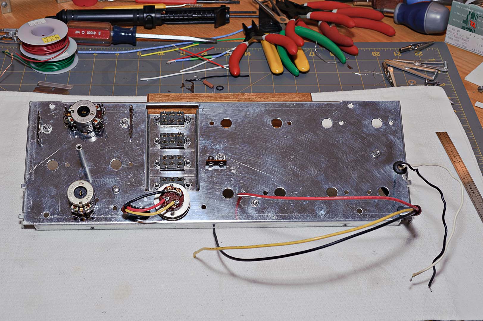
The blend control was installed next. After locking in place several wires and a 220K ohm resistor are connected from the blend control to various points on the front panel. The photo below shows the state of the front panel at this point. It is worth noting at this point that the panel is still relatively bare.
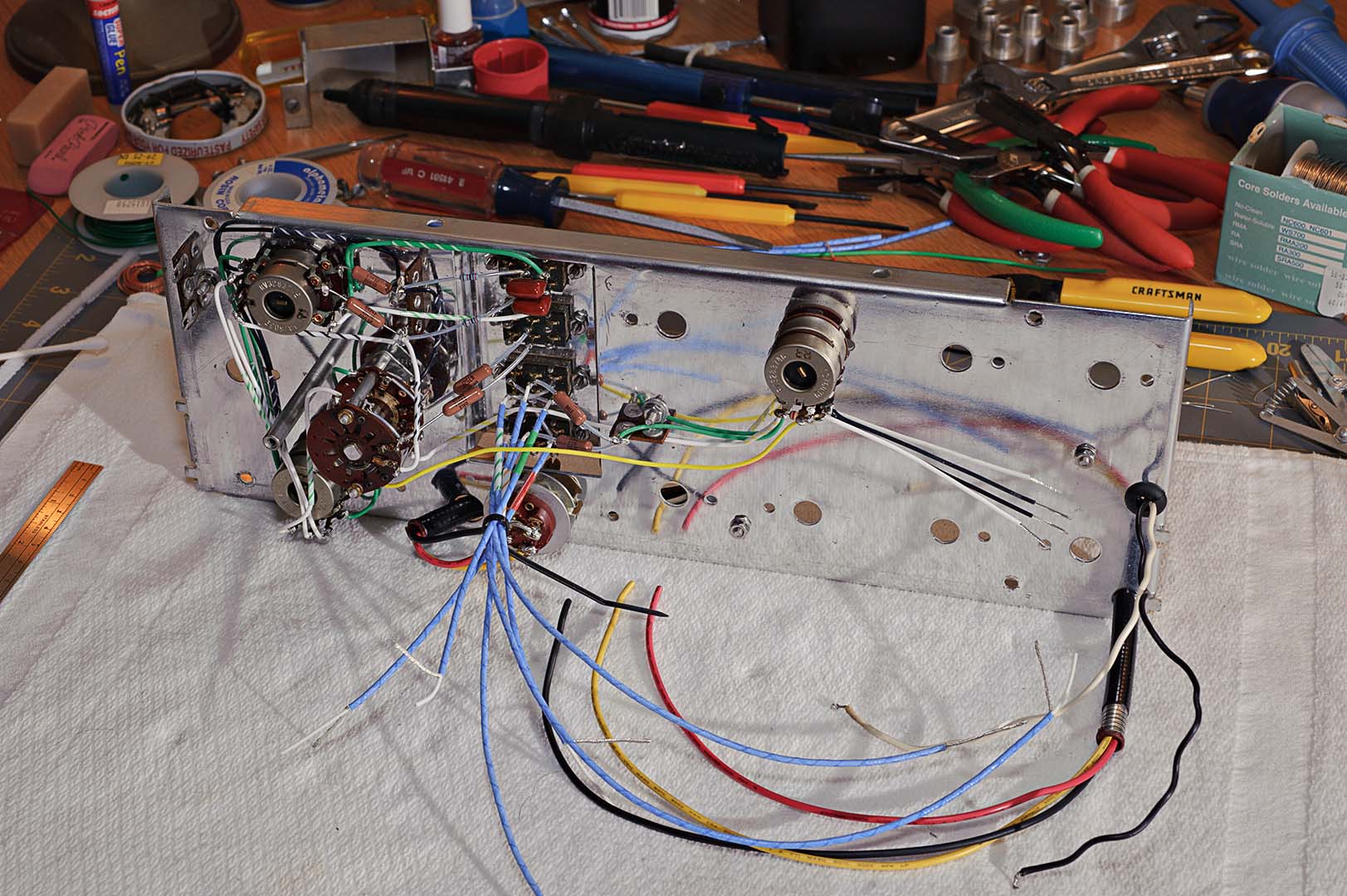
The next switches to be installed are the treble and bass switches, S4 through S7. The aluminum cover for the power switch is also installed at this time. With each switch that is installed the panel becomes more cluttered with wires that will not be attached to their destinations until later. The photo below shows the work at this point.
The turnover and rolloff switches are installed next and wired together. This is followed by the installation of the low-cut switch. Wires from the switch are connected to the bass switches. The photo below shows the state of the front panel at this point. Note how cluttered the panel now is before the wires are organized.
The next steps of the instructions call for taping together groups of these wires that will be routed to similar destinations on the two terminal boards. Of course, I will be using cable ties instead of tape.
Next comes the installation of the last switch, the function switch. This is the switch that I referred to earlier as a medusa's head. After the switch is installed the various wires, mainly the shields from the shielded wires, are connected to the proper destination points on the chassis as indicated in the manual. The twisted shields are all covered with lengths of Teflon tubing for insulation from each other.
At this point I found that a couple of the twisted shields, even after careful measuring, simply did not reach their destination on the terminal strip comfortably. I also found that even with insulation tubing placed over the shield wires there still seemed to be a danger that the wires could possibly touch each other. I stopped my work at this point to think through what to do. In the end I picked out a couple of wires that seemed to be the biggest offenders and simply removed them and replaced them with wires of slightly different lengths.
The next step is to group and tape together the wires from the function switch. The wires are grouped as indicated in one of the supplied pictorial diagrams. Because I used cable ties in place of tape I did not fully bind the wires. Instead, I left a bit of slack in the cable ties so that I would be able to adjust the ties later, after the wires had been routed to their destinations inside the chassis.
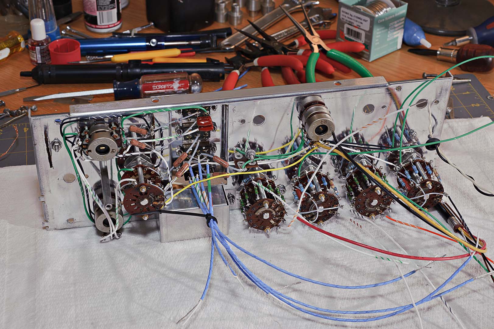
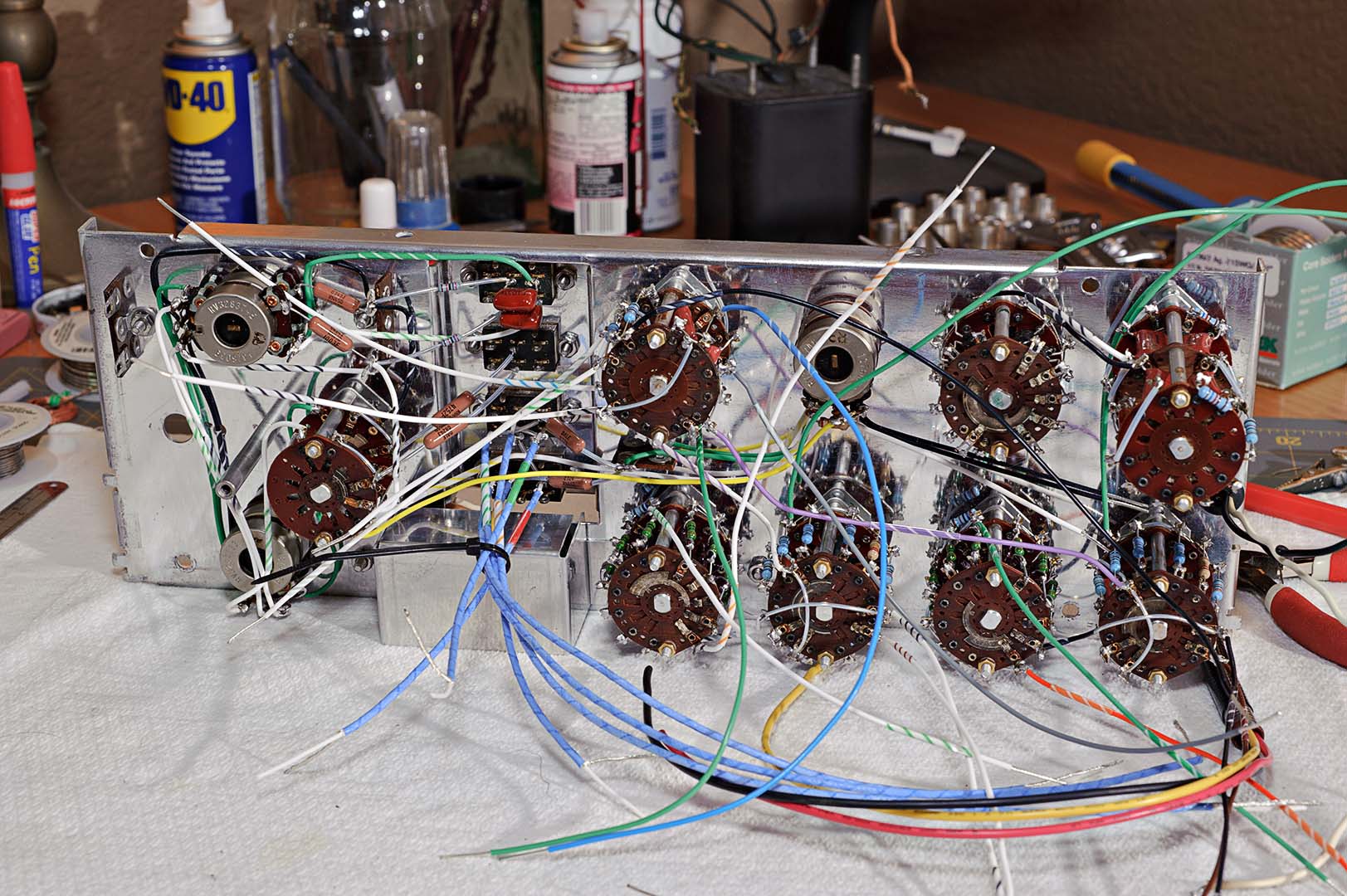
Finally, the right side rail (on the side next to the function switch) is attached. At this point the front panel looks like the following photo. There's a lot of wires there. Think what it would look like if the loose wires weren't cabled together in neat bundles.
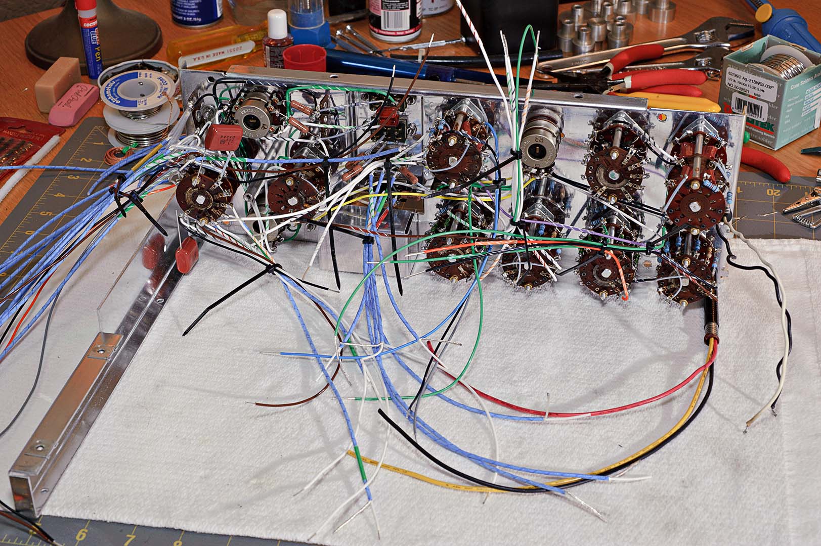
I'm now one-quarter down on page 30. The final steps of the front panel wiring are to neatly rout the wires from the function switch. The manual is very clear in pointing out how important it is to dress the wires properly so that a neat and professional appearance is obtained. This includes making sure to dress the wires in each bundle all parallel to each other, no crossing of wires. This makes for a neat appearance as well as keeping the bundle diameter to a minimum.
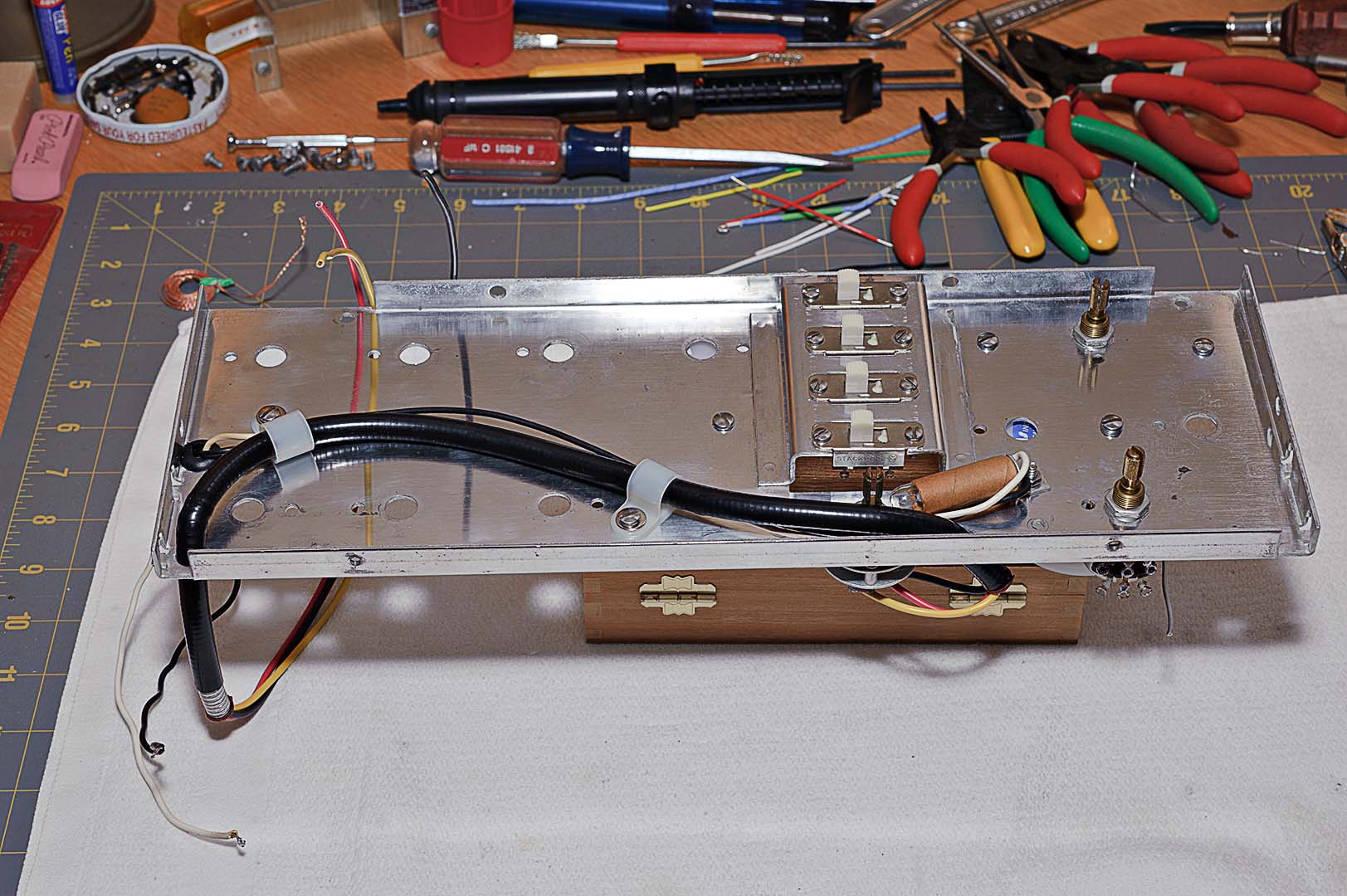
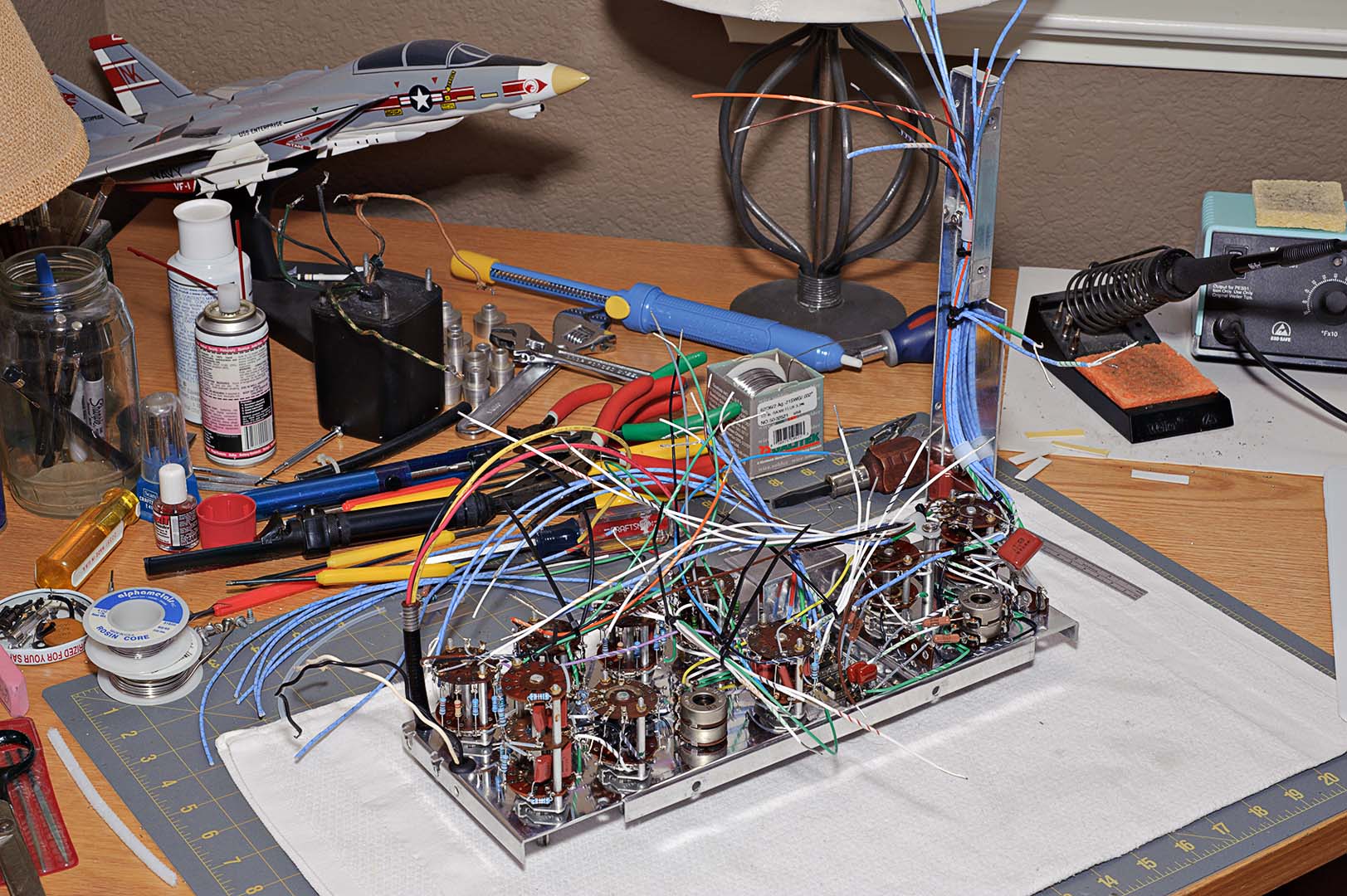
That is the only comment I can make at this point. The rest of the work is simply following the instructions as outlined in the assembly manual. New plastic cable clamps were used where specified in the instructions. When you reach the end of page 30 the front panel work has been completed. The result is shown in the following photo. Don't be confused by the extra shielded wires on the left to the rear of the panel (lying on the desk). These are extra shielded wire lengths for the next stage of construction and are not connected to the front panel.
That completes the front panel installation. As in my previous blog post I forget how long the front panel took to complete. I'll take a guess though.
Total Time Spent: ~8 hours