Saturday, November 21, 2009

Citation I Refurb - Wiring the Switches, Continued

In the previous post I went through the pre-wiring of the switches as they come from the factory.  I didn't mention that the drawings that I have created for the switches will be posted in The Citation Sound forum on Yahoo.  They're not there yet and, in fact, I haven't yet completed all the drawings using OpenOffice Draw.  But they will find their way there at some point.

And one last item about the drawings.  In reading ahead in the assembly manual I found that a tiny bit of the wiring that I did is actually outlined in the assembly manual.  This is not a big deal.  But if anyone happens to use my drawings in the future to rewire a Citation don't be confused when you return to the manual and find some wires specified in the instructions already attached to the switches.

With the factory wiring out of the way I can now return to the Assembly Manual.  I left off towards the top of page 23 so let's pick it up from there.  Things are going to be pretty straightforward from here.

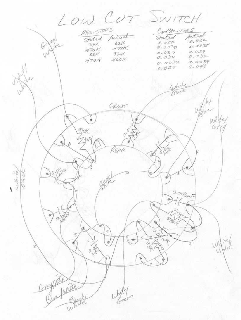
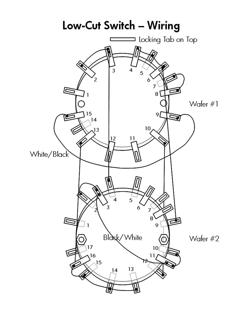
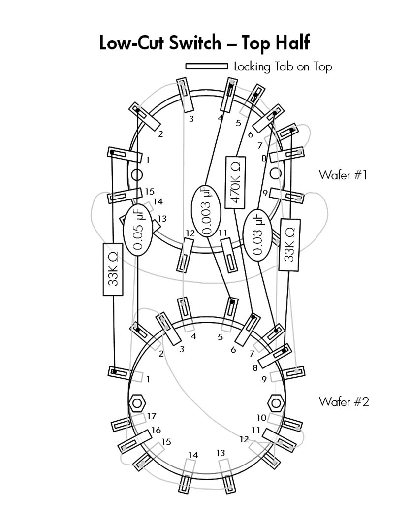
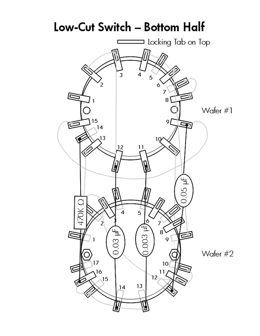
Page 23 outlines the steps for wiring the bass, treble, rolloff, and low cut switches.  There really isn't much additional commentary I can make.  These switches are the easiest to wire and consist mainly of attaching a few variously colored wires.  There is a lot of striped wire used for these switches, which I labeled using the method I have described previously.

The only decision I had to make was whether to use one or two labels for the striped wiring.  Some of the switch wires end up attaching to the terminal boards and others attach to other switches.  In general, if a wire went to one of the terminal boards I used two labels, one at each end.  This made sense as these are usually longer wires.  The wires that attach to other switches are usually short and a single label wrapped around the middle of the wire will suffice.

The striped wires that run from a switch to the terminal board present another unique problem.  To keep the inside wiring neat the wires from all the switches are collected into a number of bundles.  These bundles are then tied together and routed neatly around the chassis.  It will be next to impossible to neatly bend a teflon coated wire at the point where a label is attached.  This means I have to take extra care in where I attach the labels.

I solved this problem in two ways.  First, I only attached the switch end label at this time.  I will attach the second label later when I am tying the wires together and routing the bundles to the terminal boards.  Second, I have the luxury of having another Citation I available.  This allows me to look at where a wire is going to route immediately as it travels away from the switch lug.  Based on this I can locate the first label in a good spot that will minimally interfere with any wire bends.  If you don't have a second Citation unit for reference you'll have to look at Citation I pictorial drawings.

The wiring of the mode switch is described on page 24 and is the next step up in complexity.  There are bare wires, insulated wires, and a couple of 47K resistors that need to be attached.  Still all relatively simply.

On the bottom of page 24 begins the function switch wiring.  This one is a beast and the instructions for this one switch cover two full pages of the manual.  This switch not only has many more wires than any of the other switches, but at least half of those wires are shielded wires.  I only have one picture to accompany today's post and this is it.


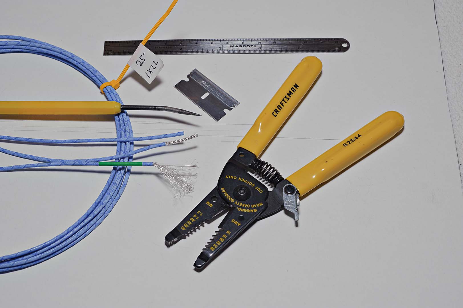
This picture represents the preparation of shielded wire.  Pictured are a short ruler for measuring the end for stripping, a wire cutter/stripper, a razor blade, a pointed pick (that came with a soldering kit) to "unbraid" the braided shield, a coil of shielded wire, and shielded wire samples in various stages of preparation.  Note that the wire pictured is what I described in an earlier post.  It is single conductor 22 gauge stranded silver coated wire with a Teflon jacket.  It is then wrapped with a braided silver coated wire shield and covered with a Teflon tape jacket.  This wire was purchased from a vendor on eBay.

An appropriate length of wire is measured (with a longer ruler not pictured) and cut.  Using the short ruler I follow the instructions in the Citation manual for how much outer insulation to strip away.  I use the razor blade to cut through just the insulation, being very careful not to nick the braided shield.  I found that in addition to cutting a "belt" around the wire I also had to cut a slit the length of the wire in order to remove the insulation.  I first tried to strip the outer insulation using the wire strippers.  This didn't work as the stripper either didn't cut all the way through the insulation or it cut some of the wires in the shield.

I then use the pick to unbraid the shield wires.  When the shield is unbraided back to the outer Teflon jacket the individual shield strands are carefully pulled together, straightened as best as possible, and then twisted tightly.  This is a time consuming task.  It doesn't take all that long to unbraid a single wire end.  But when you have to unbraid each end of the wire and you then multiply that by all the shielded wire used in the assembly of the Citation I you will find that a lot of time is spent simply unbraiding the shield.

A measured length of the inner Teflon jacket is then stripped away.  Both wires, the shield and the inner conductor, are lightly tinned.  Lastly, a colored label is attached to an appropriate location near the end of the wire (as seen in the picture).  Note that when using shielded wire you even have to use labels for solid colored wires, not just the striped wires.

The wiring of the function switch is not particularly complicated.  It's simply messy.  There are a ton of wires to attach and it quickly gets very crowded.  Clear Teflon spaghetti tubing of the appropriate diameter is used to insulate the exposed shield wire in place of the original Citation kit black insulation.

I wish I had taken a photo of the completed function switch to give an idea of how unwieldy it is.  Of course, cable ties will be used to gather the wires together in bundles for neat routing around the chassis.  But until then you have a Medusa's head on your hands.

That completes the rotary switch wiring.  Next time I'll pick up with the wiring of the front panel.

Total Time Spent:  ~8 hours

Saturday, November 14, 2009

Citation I Refurb - Wiring the Switches

It seems there has been another gap in my posts.  I'm not sure what has come up over the last two weeks that has kept me from this project, but here we are two weeks later.  What's next?  Well, according to the assembly manual it's time to pre-wire the switches.

Perhaps Harman Kardon should have called this "completion of the pre-wiring".  In fact, the H/K factory has already performed pre-wiring of the switches.  Almost all of the switches come with resistors and capacitors already soldered to their appropriate switch locations.  The Function and Mode switches are the two that do not come prewired.  What the manual calls "pre-wiring" is simply attaching lengths of wire to the switches before mounting the switches to the chassis.  It would be difficult to mount the switches first and add the wiring afterwards.

But remember, my project is a complete replacement of all components.  This means that I am going to desolder every resistor and capacitor (and wire) from each switch and rewire it with new components.  Here's a photo of two switches, a treble switch and the rollover switch, with their original components attached.


Ok, let's start desoldering and get this project moving again!  Whoa, whoa, whoa... slow down!  Just how am I going to rewire these switches?  They all came pre-wired from the factory.  There are no pictorials from Harman Kardon that I am aware of that show how to wire one of these switches.  Solution?

You guessed it.  I'm going to have to draw up a diagram for each of these switches before I tear it apart.  And I had better take my time and check, and re-check, my drawings.  Fortunately, I have other Citation I units that I can open up and use as references, even after I've removed all the components from the switches.  So, first step is to get a pencil, an eraser, and blank paper.  Let's start drawing.

Creating the drawings was a long task.  It's not particularly hard.  You just have to go at it slow.  I had to make liberal use of the eraser.  It's not really so much because of any carelessness on my part.  Keeping the switch oriented properly as you transcribe component locations from the switch to paper, counting out the switch lugs properly, etc all contribute to mistakes on paper.  At the start I had to decide how best to depict the wafers and the orientation of the switch.  I finally decided to draw wafer #1 (the wafer nearest the chassis, or what I called the front wafer) as a large circle and I then drew wafer #2 (the rear) as a smaller circle inside of wafer #1.  To keep orientation the same in all the drawings I decided on a standard of placing the locking tab on the right side of the drawing with the shaft pointing away from you.  Here's an example of my drawings, in this case the low-cut switch.


After I had all the hand drawings completed I decided that I wanted a little more for permanent documentation purposes.  So my next task was to convert all of these hand drawings to some sort of computer file.  I wanted something that looked similar to the H/K supplied pictorials.  I would have prefered to use MS Visio, but I don't have that program at home.  Instead, I chose to install the Open Office suite (OpenOffice.org) and created all the drawings in OpenOffice Draw.  To keep the drawings from becoming too cluttered I broke the drawings apart into multiple views.  For example, the Low-Cut switch above was broken apart into three views; the wires alone, the top half of the switch, and the bottom half of the switch.  Here's what the finalized pictorials look like.


Now that the drawings are all complete all that needs to be done is to remove all the components from all switches and solder in the new components.  Yeah, that's all.  In actual practice it takes a lot longer than it just took me to type that sentence.  Drawing up a single switch, double checking it, removing all the old components, cleaning up all the switch contacts with DeoxIT, and soldering in the new components was an entire evenings work for a single switch.  And that doesn't count the time spent on the OpenOffice drawings (I did the OpenOffice drawings after I had completed all the switches.).  There are a total of 9 rotary switches that need to be taken apart and cleaned.  However, only 7 of those switches need to be rewired at this point.  The Function and Mode switches do not contain any resistors or capacitors installed from the factory.

When adding the wiring I did not use color insulated wiring for wires that went from one switch lug to another.  Instead, I used bare wire.  If a wire was long enough or was located in a position where it might touch exposed metal I used teflon tubing as insulation.  Here's a photo of the completed Rolloff switch.  There is no insulated wire on this switch but you can see the bare wire used to connect various lugs.


The treble switches were the most fun to work on.  For some dumb reason I enjoyed assembling the paralleled capacitor-resistor configurations.  As you can see in the following drawing I used the same technique as employed by Harman Kardon in the factory.  This photo shows my own construction alongside the original components that I removed from the switch.


I think that just about covers the work done on the rotary switches.  For the potentiometers I didn't do a lot of work.  The only thing I did was to apply some DeoxIT to the pot and rotate the pot back and forth a number of times.  The four slide switches were handled similarly.  I used rubbing alcohol to clean all the finger grease and dirt off the white finger slide and used DeoxIT on the actual backside slide switch.  I was pleased with how well the front side of the switch, the cosmetic side, cleaned up.  They now look almost brand new.

Here are all the completed front panel switches laid out in their approximate front panel locations.  Taken as a whole, this has been the most time consuming piece of the whole reconstruction project.  With each rotary switch taking 3 or 4 hours to complete it was approximately a two week long process to finish up all the front panel switches.  But I can honestly say I am very, very pleased with the results.


Total Time Spent: ~40-50 hours