Perhaps Harman Kardon should have called this "completion of the pre-wiring". In fact, the H/K factory has already performed pre-wiring of the switches. Almost all of the switches come with resistors and capacitors already soldered to their appropriate switch locations. The Function and Mode switches are the two that do not come prewired. What the manual calls "pre-wiring" is simply attaching lengths of wire to the switches before mounting the switches to the chassis. It would be difficult to mount the switches first and add the wiring afterwards.
But remember, my project is a complete replacement of all components. This means that I am going to desolder every resistor and capacitor (and wire) from each switch and rewire it with new components. Here's a photo of two switches, a treble switch and the rollover switch, with their original components attached.

Ok, let's start desoldering and get this project moving again! Whoa, whoa, whoa... slow down! Just how am I going to rewire these switches? They all came pre-wired from the factory. There are no pictorials from Harman Kardon that I am aware of that show how to wire one of these switches. Solution?
You guessed it. I'm going to have to draw up a diagram for each of these switches before I tear it apart. And I had better take my time and check, and re-check, my drawings. Fortunately, I have other Citation I units that I can open up and use as references, even after I've removed all the components from the switches. So, first step is to get a pencil, an eraser, and blank paper. Let's start drawing.
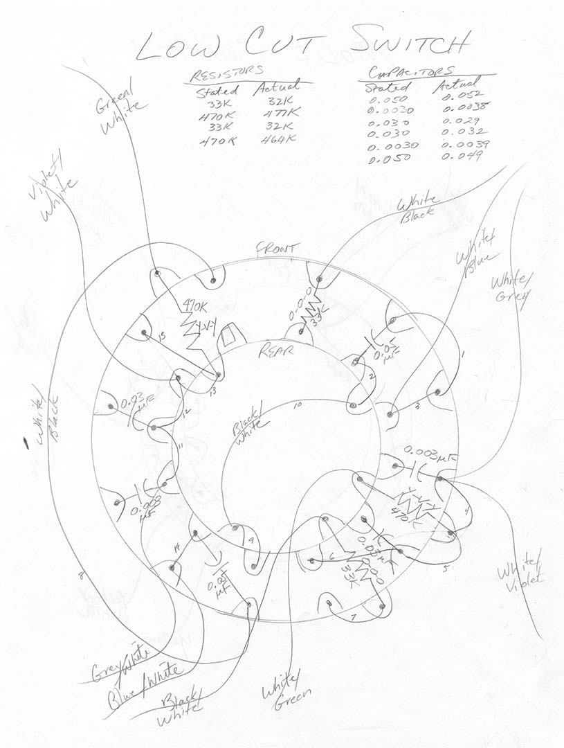
Creating the drawings was a long task. It's not particularly hard. You just have to go at it slow. I had to make liberal use of the eraser. It's not really so much because of any carelessness on my part. Keeping the switch oriented properly as you transcribe component locations from the switch to paper, counting out the switch lugs properly, etc all contribute to mistakes on paper. At the start I had to decide how best to depict the wafers and the orientation of the switch. I finally decided to draw wafer #1 (the wafer nearest the chassis, or what I called the front wafer) as a large circle and I then drew wafer #2 (the rear) as a smaller circle inside of wafer #1. To keep orientation the same in all the drawings I decided on a standard of placing the locking tab on the right side of the drawing with the shaft pointing away from you. Here's an example of my drawings, in this case the low-cut switch.
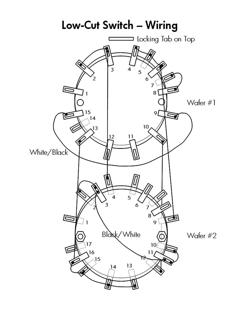
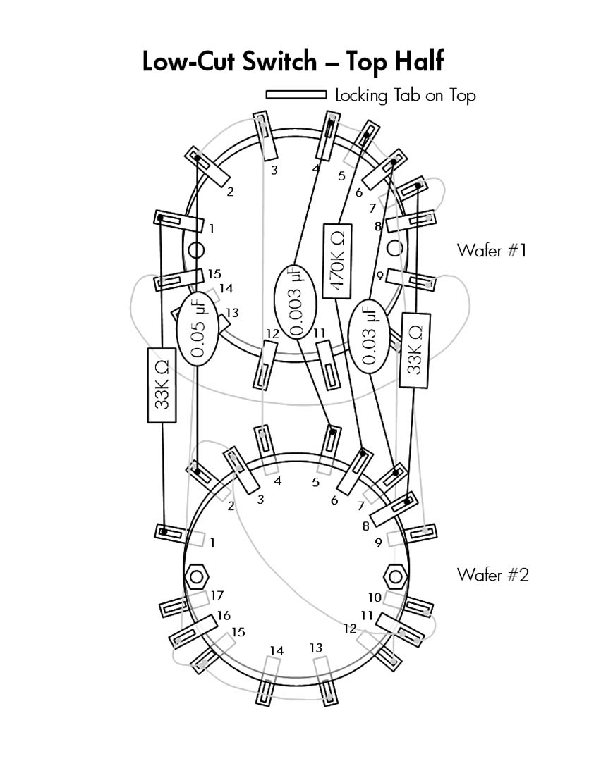
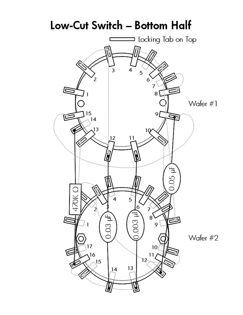
After I had all the hand drawings completed I decided that I wanted a little more for permanent documentation purposes. So my next task was to convert all of these hand drawings to some sort of computer file. I wanted something that looked similar to the H/K supplied pictorials. I would have prefered to use MS Visio, but I don't have that program at home. Instead, I chose to install the Open Office suite (OpenOffice.org) and created all the drawings in OpenOffice Draw. To keep the drawings from becoming too cluttered I broke the drawings apart into multiple views. For example, the Low-Cut switch above was broken apart into three views; the wires alone, the top half of the switch, and the bottom half of the switch. Here's what the finalized pictorials look like.
Now that the drawings are all complete all that needs to be done is to remove all the components from all switches and solder in the new components. Yeah, that's all. In actual practice it takes a lot longer than it just took me to type that sentence. Drawing up a single switch, double checking it, removing all the old components, cleaning up all the switch contacts with DeoxIT, and soldering in the new components was an entire evenings work for a single switch. And that doesn't count the time spent on the OpenOffice drawings (I did the OpenOffice drawings after I had completed all the switches.). There are a total of 9 rotary switches that need to be taken apart and cleaned. However, only 7 of those switches need to be rewired at this point. The Function and Mode switches do not contain any resistors or capacitors installed from the factory.
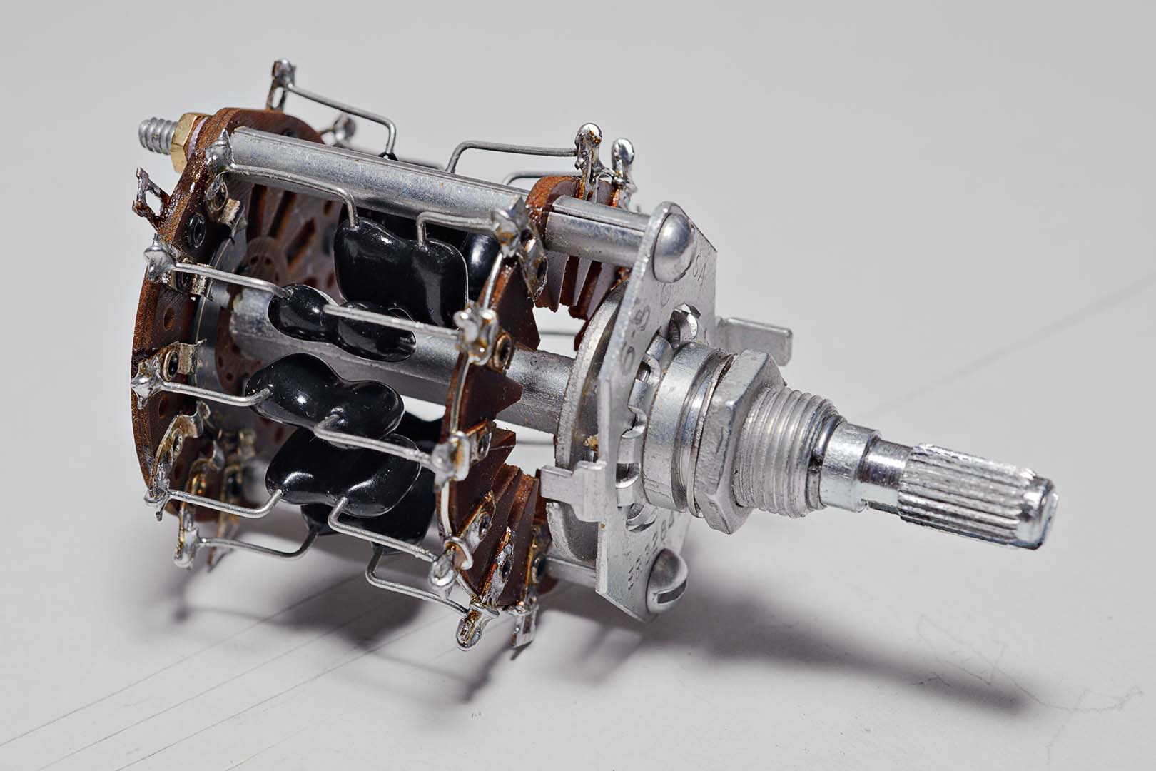
When adding the wiring I did not use color insulated wiring for wires that went from one switch lug to another. Instead, I used bare wire. If a wire was long enough or was located in a position where it might touch exposed metal I used teflon tubing as insulation. Here's a photo of the completed Rolloff switch. There is no insulated wire on this switch but you can see the bare wire used to connect various lugs.
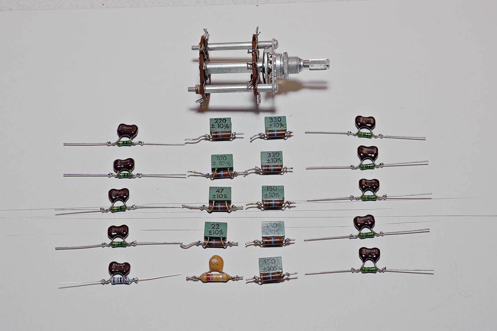
The treble switches were the most fun to work on. For some dumb reason I enjoyed assembling the paralleled capacitor-resistor configurations. As you can see in the following drawing I used the same technique as employed by Harman Kardon in the factory. This photo shows my own construction alongside the original components that I removed from the switch.
I think that just about covers the work done on the rotary switches. For the potentiometers I didn't do a lot of work. The only thing I did was to apply some DeoxIT to the pot and rotate the pot back and forth a number of times. The four slide switches were handled similarly. I used rubbing alcohol to clean all the finger grease and dirt off the white finger slide and used DeoxIT on the actual backside slide switch. I was pleased with how well the front side of the switch, the cosmetic side, cleaned up. They now look almost brand new.
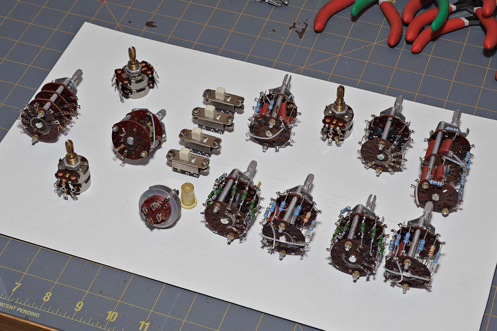
Here are all the completed front panel switches laid out in their approximate front panel locations. Taken as a whole, this has been the most time consuming piece of the whole reconstruction project. With each rotary switch taking 3 or 4 hours to complete it was approximately a two week long process to finish up all the front panel switches. But I can honestly say I am very, very pleased with the results.
Total Time Spent: ~40-50 hours

No comments:
Post a Comment