Way back on Nov. 21 I had just completed the switch wiring and was now ready to begin on the front panel, which is described at the bottom of page 26 of the assembly manual. I think I made mention in the last post that all of the hard work has been completed and the remainder of the step are pretty straight forward. This is mostly true.
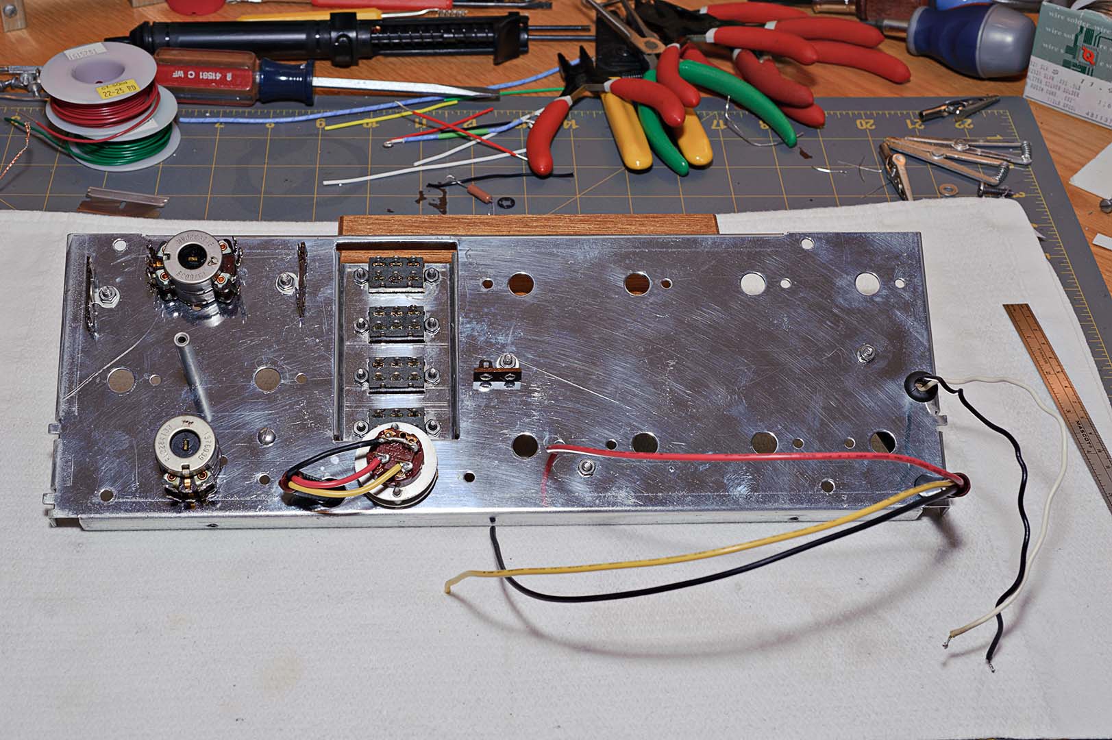
The four slide switches were installed in the front panel followed by a new small rubber grommet. The AC switch was installed and a new #1815 pilot bulb was installed, even though the old one was still working. The pilot lamp assembly was mounted onto the panel and the wires routed through the new grommet.
The wires that run to the power switch were prepared next. This is the one place in the project that I did not use Teflon coated wire. Basically, I just couldn't find any wire of sufficient gauge that I could buy in small quantities. I ended up buying 25ft spools of 16 gauge PVC coated wire (80°C, 300V). I also could not find the original colors of blue, tan, and black. Instead, I had to settle for black, yellow, and red. Yellow replaced tan and red replaced blue. The wires were run through the original insulated metal tubing, mounted to the chassis using new plastic clamps, and soldered to the power switch.
The lug strips (TS4, TS5, and TS6) were installed. Finally the tubular spacer was attached and the loudness and balance controls were mounted. The end result at this stage are the two photos below, one from each side of the panel.
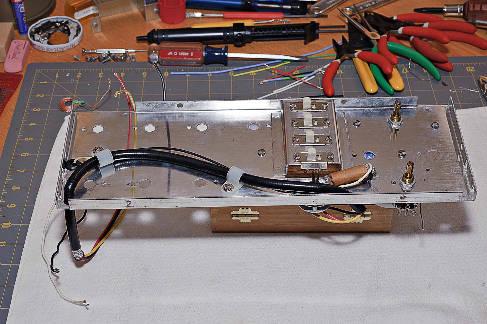
The next steps in the manual cover the wiring of the loudness and balance controls as well as the preliminary wiring of the slide switches. In the photo below you can see more examples of the labels that I used to indicate the striped wiring. You can also see that there is also a fair amount of shielded wiring that runs from the slide switches, specifically S13 and S14 (stereo reverse and phasing switches).

At this point I am going to stop. My bookmark is on the middle of page 28 of the assembly manual. With any luck I can complete this assembly in just a couple more blog posts. I would like to be able to say how much time the above work took to complete. Unfortunately, it was four months ago and I just don't remember. I'll give an estimate anyway.
Time Spent: ~2-3 hours

No comments:
Post a Comment