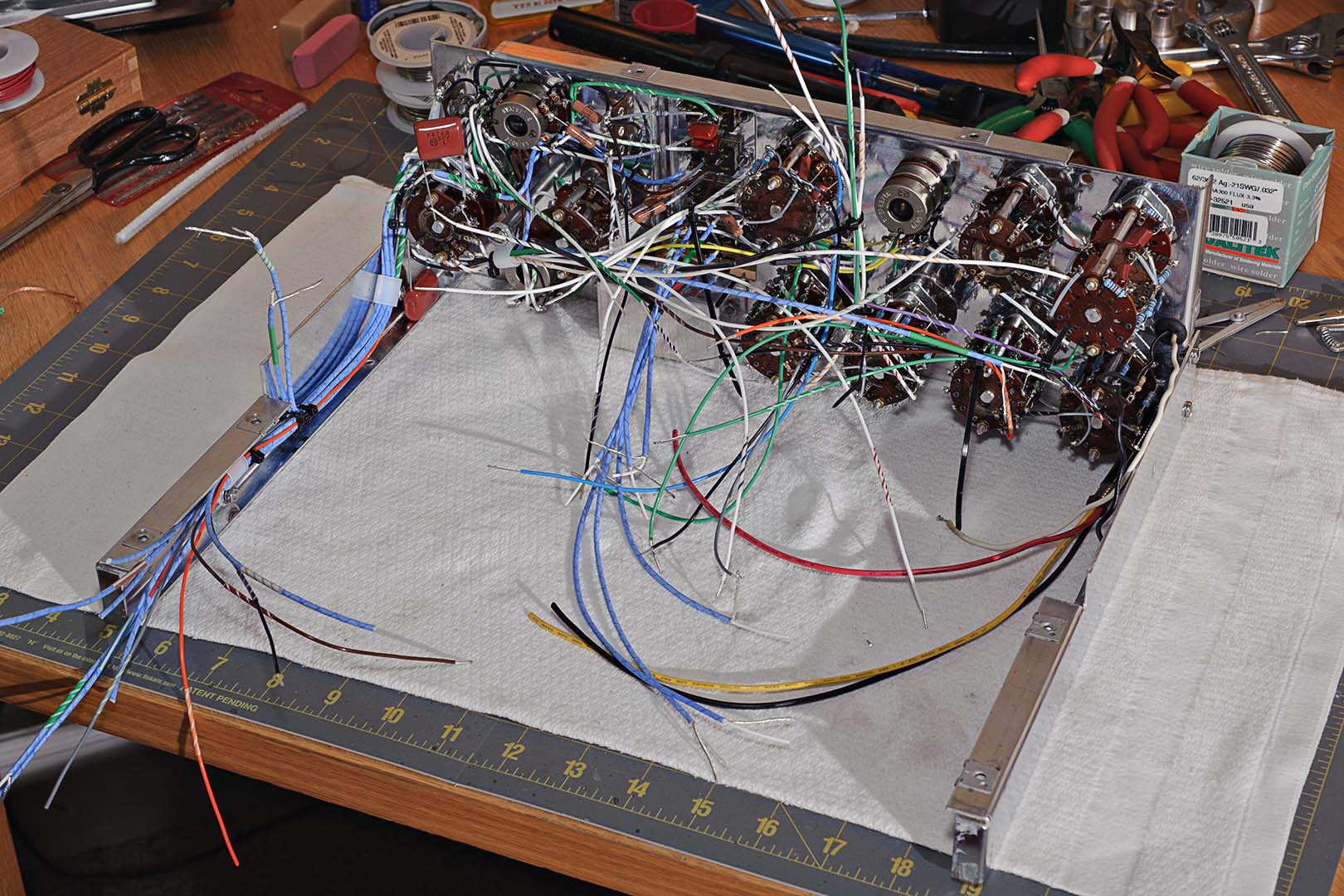
Speed nuts are installed and the left hand rail is attached. The flexible metal tubing from the front side of the panel is clamped to the rail and the bare metal portion is soldered to the clamp. I'm not sure if the soldering is for grounding of the metal tubing in order to shield the wires from eletrical interference or simply to provide a secure attachment. The front panel and side rail assembly is shown in the following two photos.

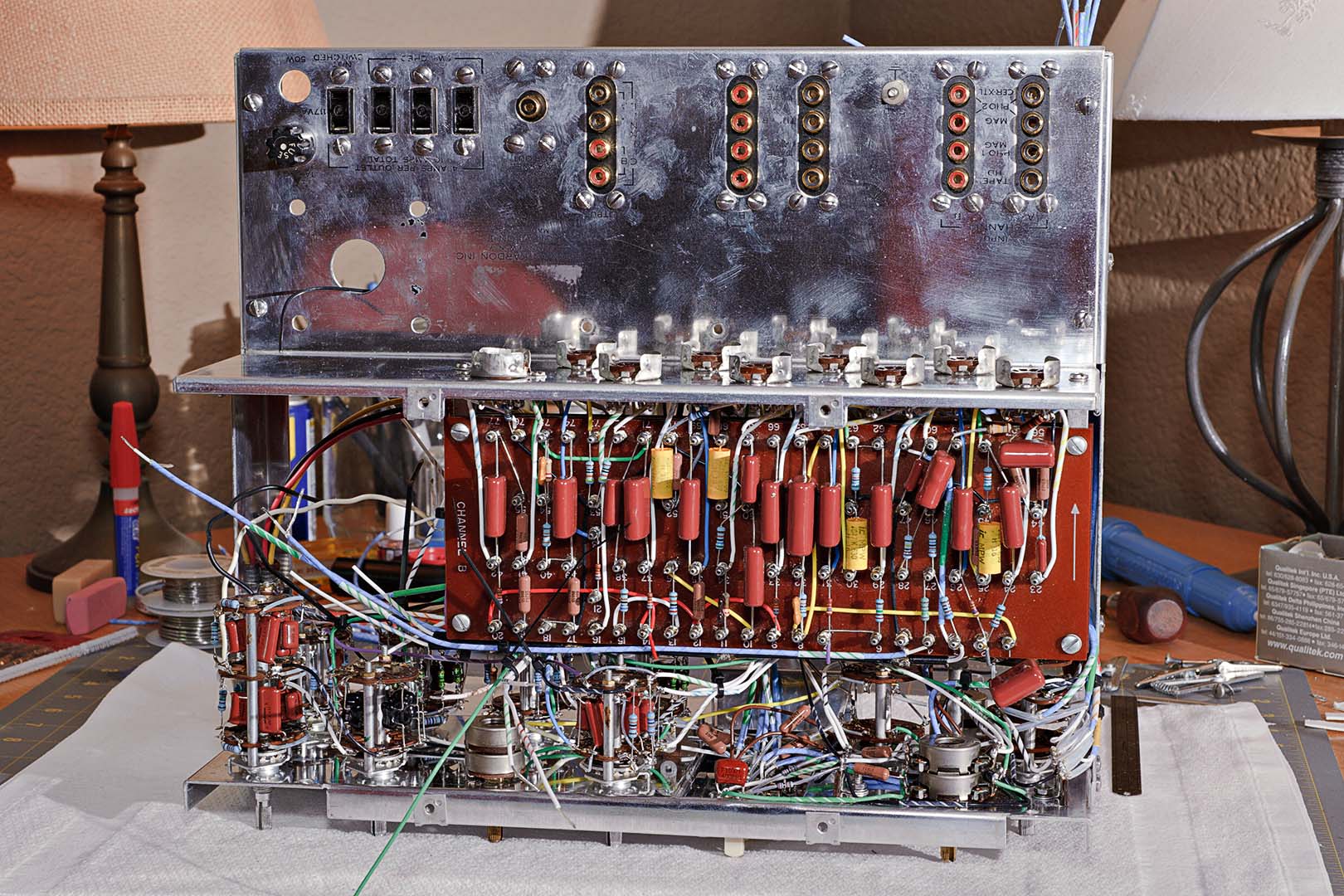
The main chassis is attached next. The main chassis up to this point is comprised of the rear deck (RCA inputs and outputs), the tube sockets, and the A and B terminal boards. After attachment of the main chassis the unit is seen from the front and top views in the next two photos. It's really starting to look like it's nearing completion now.
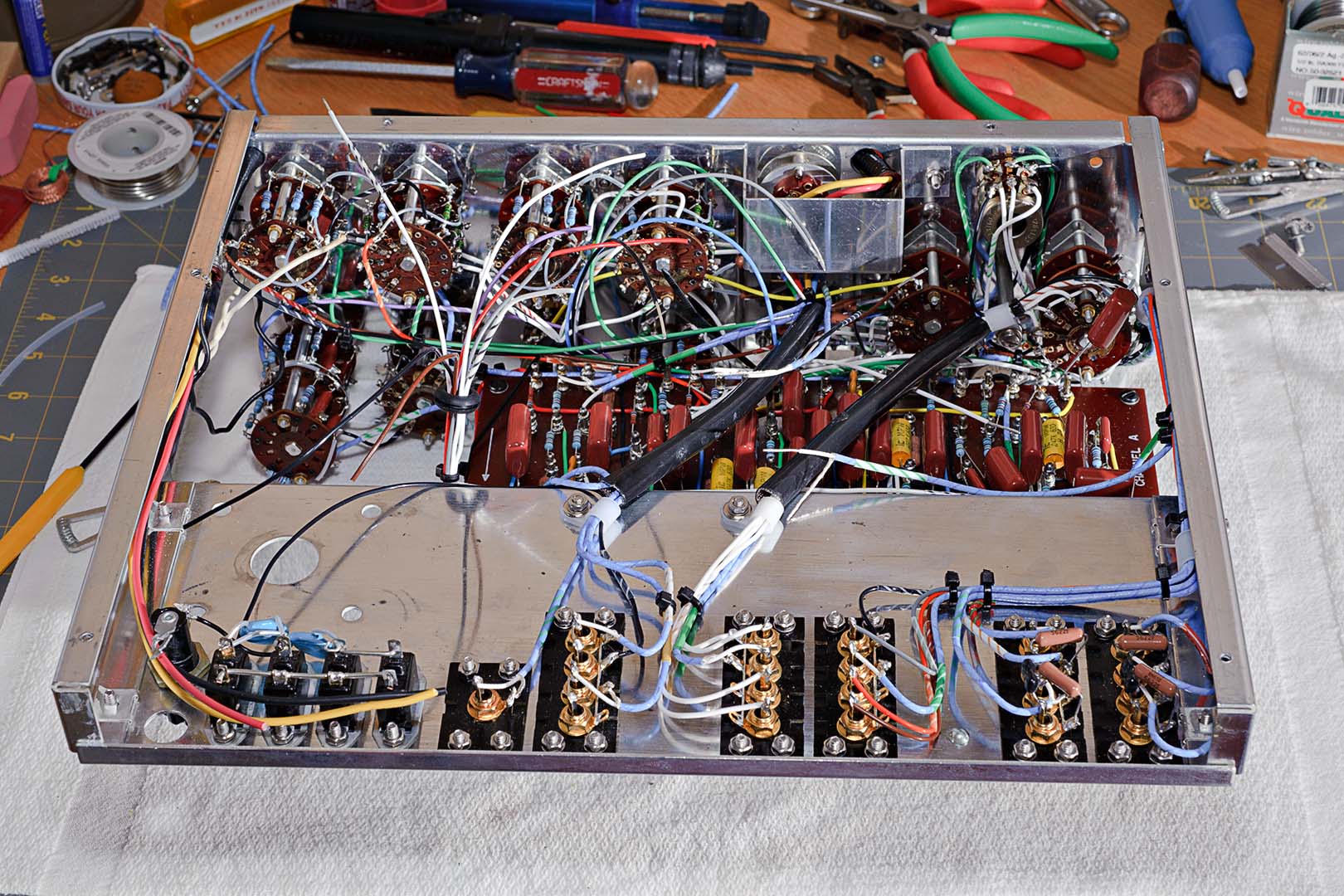
And now a view from underneatch at the Channel A side of the chassis. Now this looks to be a bit of a mess. It looks like a plate of spaghetti. The reason the underside looks so messy compared with the top is that most of the remaining wires that need connection are located on the underside as they run to the RCA jacks on the rear deck.
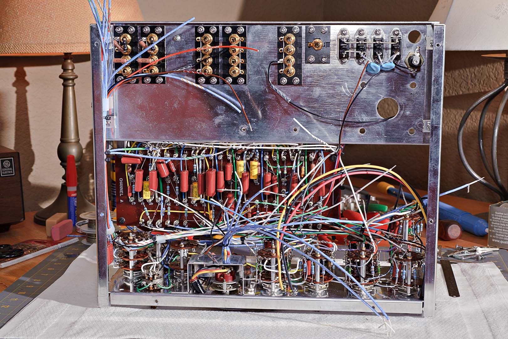
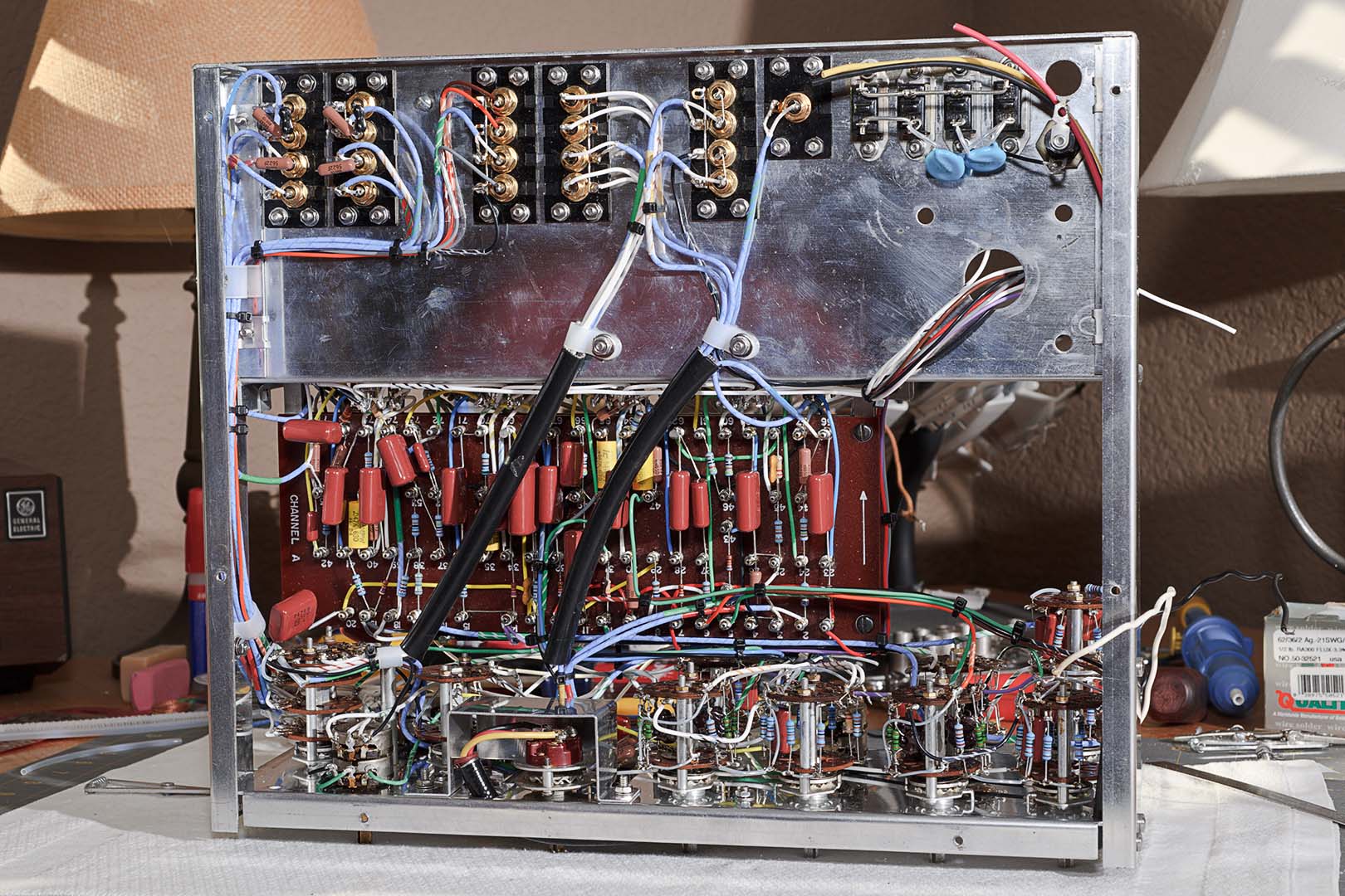
The remainder of page 31 and the first half of page 32 are a long list of steps to route and connect the wire running to the RCA strips on the rear deck. There's nothing out of the ordinary to point out here. Follow each step in the manual and be neat in the bundling and routing of the wires. New plastic nylon clamps were used to secure the main wire bundles running to the rear deck. Harman Kardon did a good job in the instructions of laying out a neat chassis. Following their steps and using small cable ties in place of the original black tape should result in a tidy appearance.
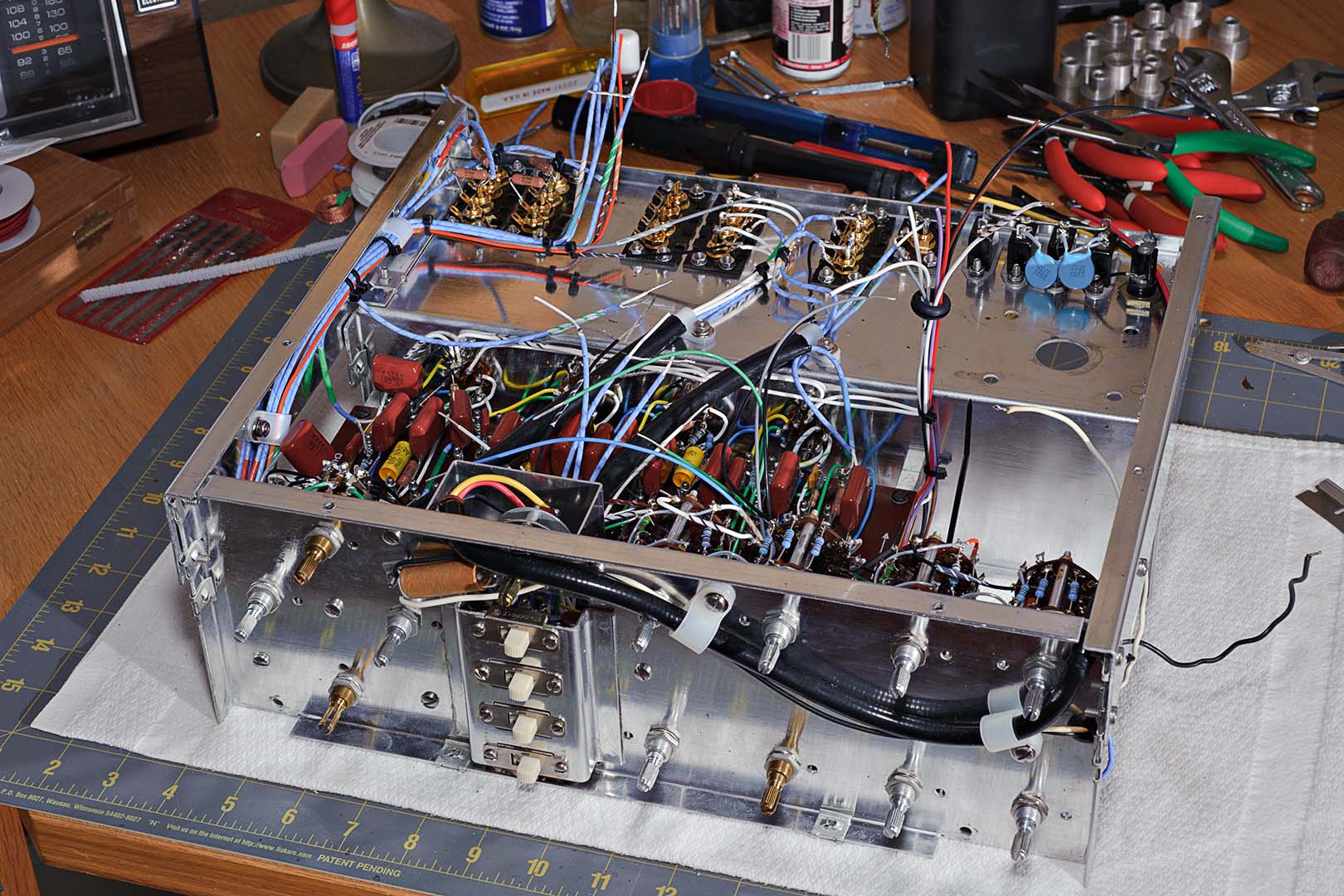
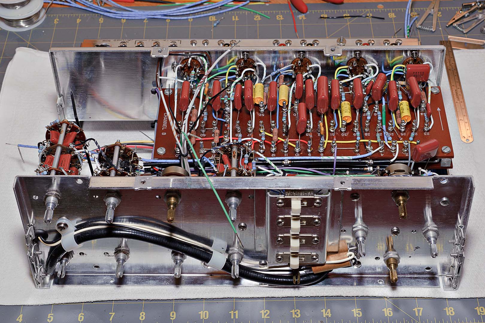
The second half of page 32 and all of page 33 deal with connecting the remaining front panel switch wires to their proper terminations on the terminal boards. Again, there's nothing complicated or noteworthy here. As commented on above, simply follow the instructions step by step. If there's is any advice to give out it would simply be to repeat the neatness theme. If you work carefully, following the instructions, you almost can't help but be neat. The following two pictures show what the underside of the chassis looks like after the wiring of terminal board A is complete.
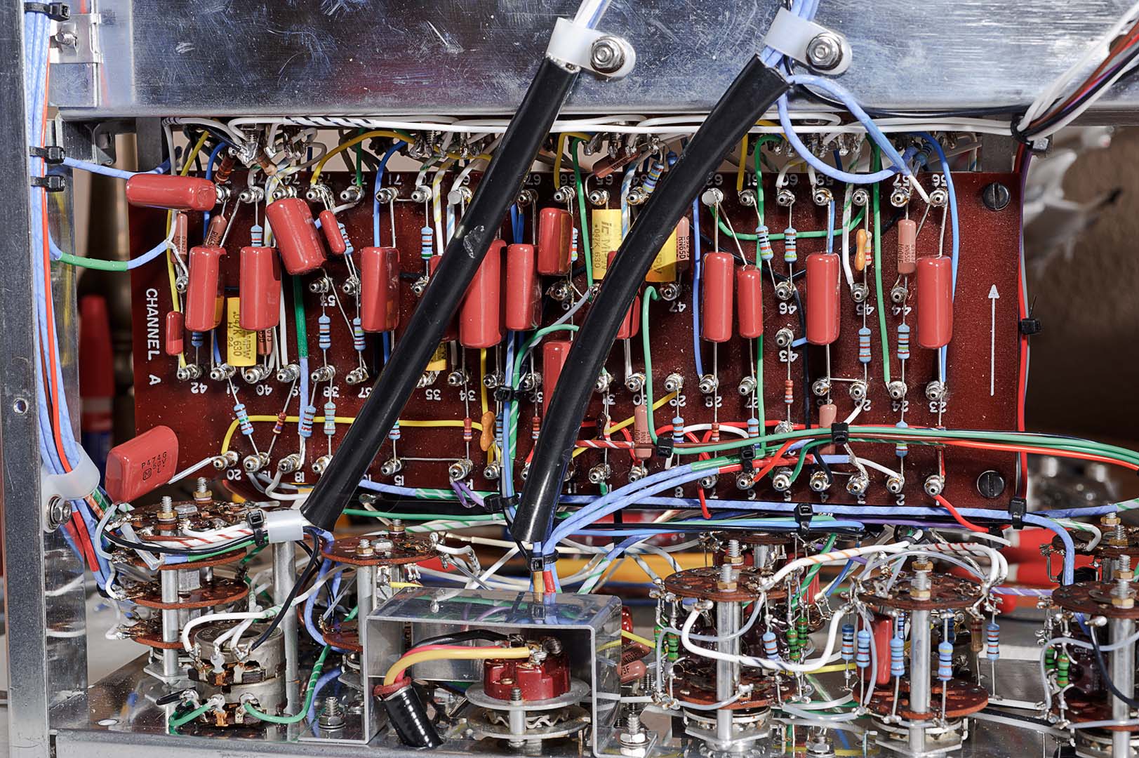
Once the underside and terminal board A are complete the chassis is flipped over and wiring of terminal board B is completed. The completed topside is shown below. In the two photos above and the one below you can no doubt see the striped labels that were wrapped around many of the wires. You may have to click on the image to zoom in. The use of laser labels for creating "striped insulation" wires seems to have worked out well. The proof of how well it worked won't come for a couple of years. When the chassis is opened up in 3 or 4 years' time will the labels still be wrapped snugly around the wires. I'm actually betting that they will be.
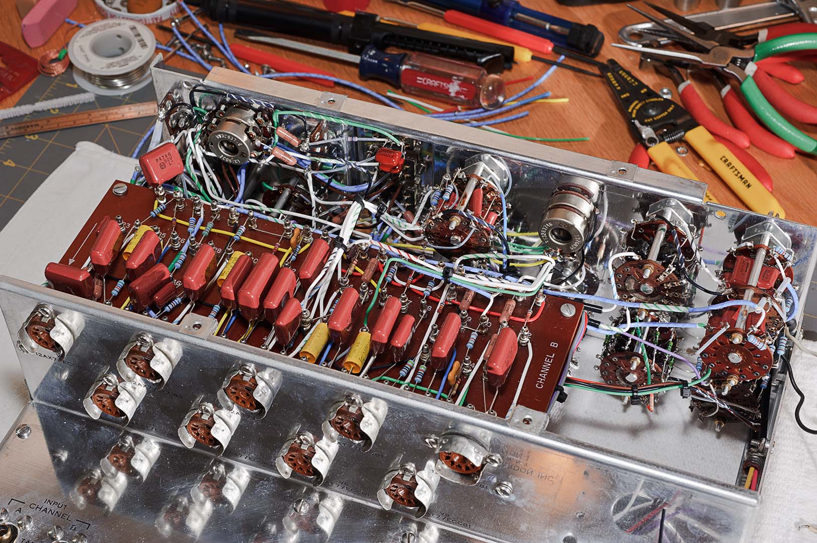
That completes the wiring of the switches and the terminal boards. We're almost finished. The remaining work is to install the power supply section that was completed a long time ago. And after that is the final assembly of the enclosure and knobs.
Total Time: ~12 hours

No comments:
Post a Comment