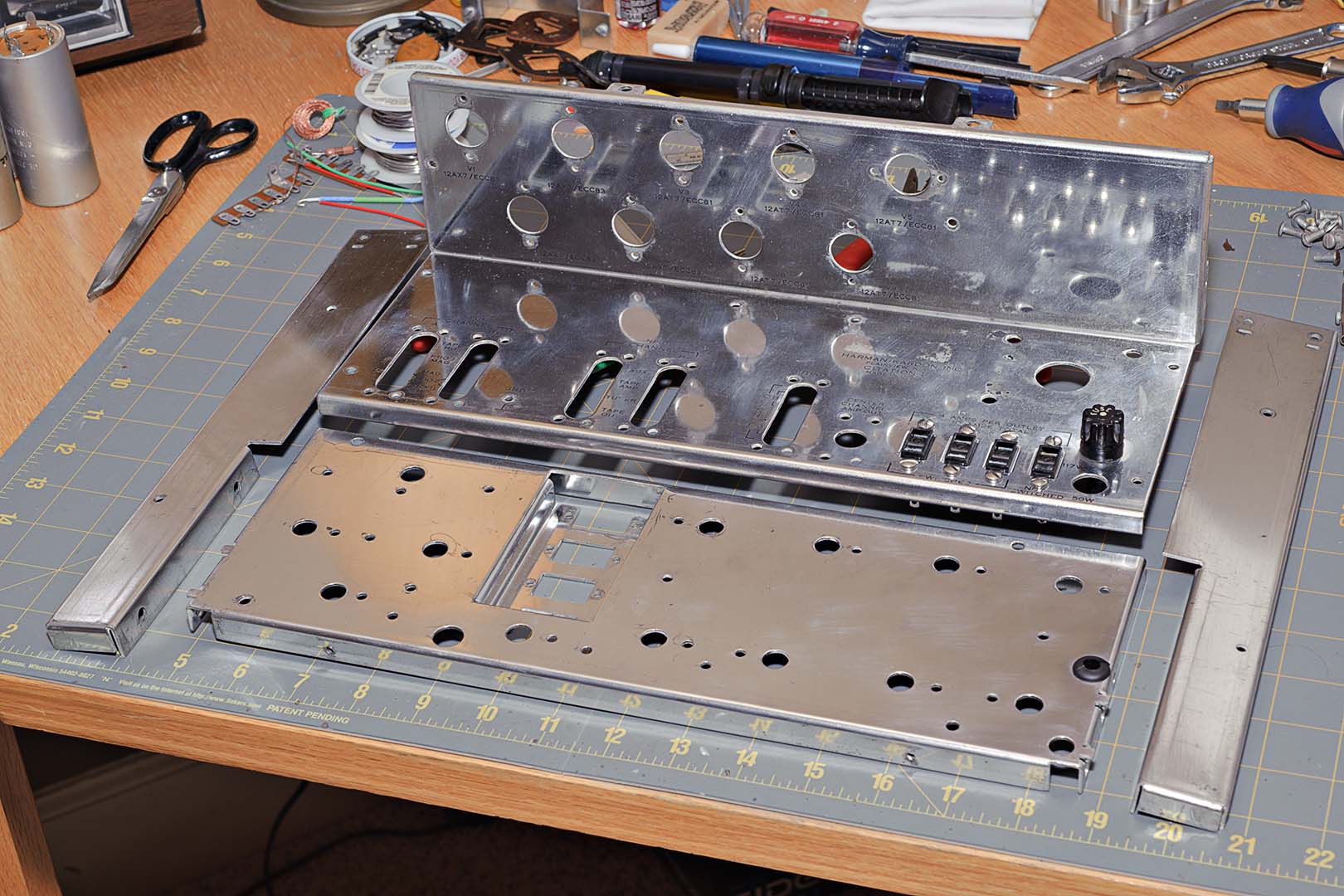
Beginning on page 18 of the manual, the first steps are pretty easy. Using the large L-shaped chassis section, the tube sockets, RCA socket strips, convenience outlets, and fuse holder are installed. In the photo above you can see that the convenience sockets and fuse were installed out of order according to the instructions. Of course, I never took the fuse holder out when I took the chassis apart. Also remember that I am using almost entirely new binding head machine screws, lockwashers, and nuts purchased from http://www.aaronsmachinescrews.com/. I purchased both the #6-32 screws used predominantly in the assembly of the unit and #4-40 screws for the tube sockets.
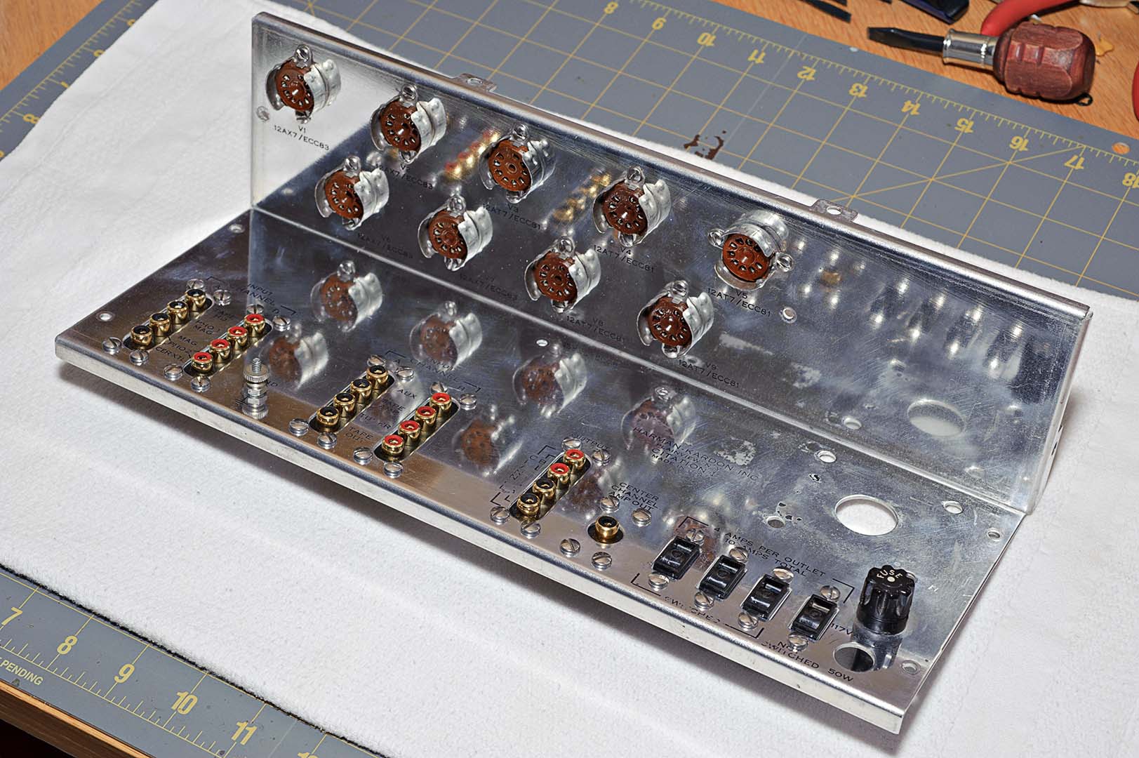
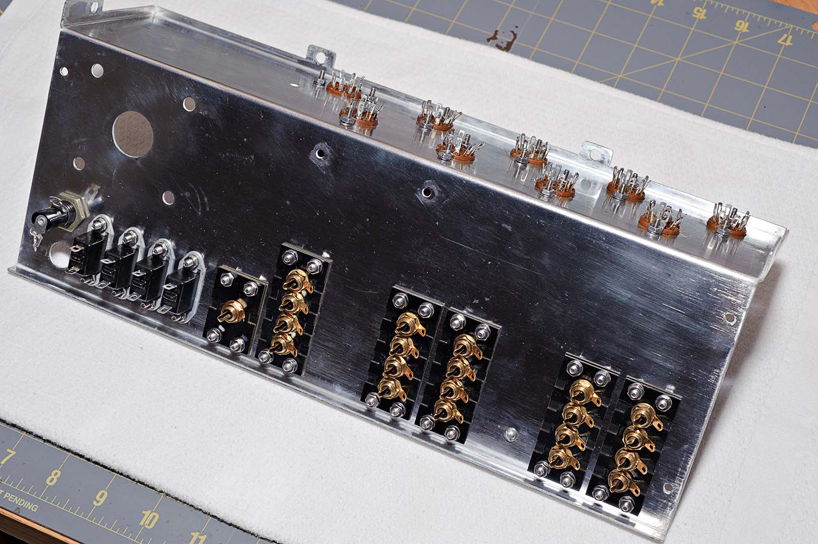
After completion of the five steps under Chassis Assembly I had what is shown in the following two photos; the first is the top side and the second is the underside. You can tell from the photos that I am using black socket inserts for the A channel and red inserts for the B channel (Red is Right).
After the above steps had been completed I started on the chassis wiring. The chassis wiring begins with the wiring of the tube sockets. Black wire is used to tie together Pins 4 on all the tubes, brown wire is used to tie together Pins 5 on Channel B, and white wire is used to tie together Pins 5 on Channel A. Unfortunately, I forgot to take a photo after this wiring step was completed.
So here's a question I had as I assembled not only this Citation I, but also my previous Citation II amps. Do the wire colors used in electronics have standardized meanings? I finally took the time to look it up. For the most part the answer is yes. Here are some standard color uses.
Black = Grounds and returns
Brown = Heaters or Filament
Red = High Voltage (Power Supply B+)
Orange = Screen Grid
Yellow = Cathode
Green = Control Grid
Blue = Plate
Violet = Power Supply negative
Gray = AC power lines (sometimes Black/White is used)
White = Bias, Miscellaneous, above grounds, AGC
These color usages were obtained from this handy PDF file I found on-line - http://www.tentlabs.com/InfoSupport/page35/files/wiringcolours.pdf. This file contains wiring colors for transformers as well. So, how do these standard colors match up to the pinouts for the tubes used in the Citation I; 12AX7 and 12AT7? These tubes are dual section triodes and have identical pinouts that are as follows:
Plate = Pins 1, 6
Grid = Pins 2, 7
Cathode = Pins 3, 8
Heater = Pins 4, 5
Pin 9 is not used in the Citation I
So in this case the brown to pins 5 make sense. But I'm not sure about the usage of black on pins 4 or white on the A channel pins 5. When we get to the hook up of the remaining pins in a later section we see that Harman Kardon followed the blue, yellow, green standard.
That's all I'm going to write about this time. Where did we leave off? We have just completed Pictorial 4, Figure B and are in the top half of page 19 about to start on Pictorial 4, Figure C.
Total Time Spent: ~1 hour for the above work.

No comments:
Post a Comment