The next section of the manual starts with the assembly of the chassis. So I really can't go any further until I clean up the rest of the chassis. Let's go back and look at my original high level plan.
- Completely disassemble the Citation I into its parts. Just like when the kit box was opened.
- Order all the replacement parts. This can happen in parallel with the first step.
- Clean all of the hardware as close to an "as new" state as possible.
- Assemble the Citation I according to the Harman Kardon assembly manual.
To begin the rest of the teardown I started with the rear deck of the chassis that contains the transformer, the convenience outlets, and the RCA jacks. The transformer was removed earlier when the power supply bracket was removed.
The RCA jack strips were removed. It is very important to keep these unless you want to fabricate your own RCA strips from scratch. If you want to do this check out Sheldon Stokes' site at http://www.quadesl.com/. He has a template available for download if you want to cut your own RCA mounting strips from a suitable blank such as GR-4 circuit board material.
Next I removed the convenience outlets. Remember from an earlier post that 3 out of 4 of these outlets are chipped so I will be installing new Kulka outlets. For now, I'm leaving in the fuse holder and the power cord. Here's a photo of the work chassis at this point.
Continuing on, the next step is to remove the 9-pin sockets. This is an easy task as all the wires have been removed. The sockets are set aside for the assembly phase. But before I set them aside I deposited a bit of Deox-IT Power Booster on each pin socket. I tried to use a length of pipe cleaner with Deox-IT applied, as suggested by someone. But the pipe cleaners I tried were simply too big to fit in the small pin holes. And on top of that the fibers tore from the wire and remained in the socket. So after trying this on one pin socket I gave up and simply brushed some Deox-IT into each hole.
If you recall, I broke one of the pin lugs off the V3 socket when removing the old wires. I purchased a replacement for this one. But imagine my surprise as I applied Deox-IT to each socket and found a missing pin lug on socket V5. Now I know I did not break that pin off. So this is one more example of the state of this amp. It really does need a refurbishing. I didn't want to beg my source for another socket so I went out to the garage and pirated a socket from one of my other units. I'll have to replace that socket eventually but that's for another day.
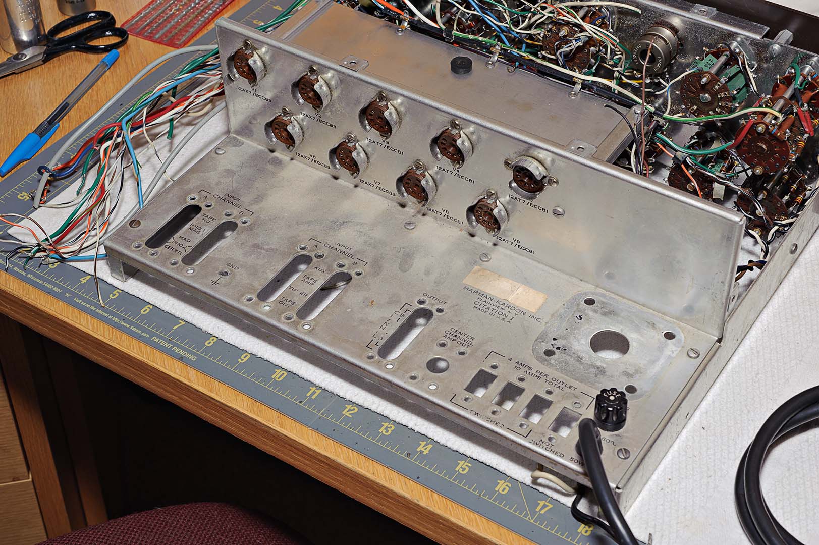
After the sockets were all removed and cleaned I then removed the face plate. The face plate is not hard to get off. What is interesting during normal operation of the Citation I is that you have to remove the faceplate in order to replace a burnt out lamp for the power-on light.
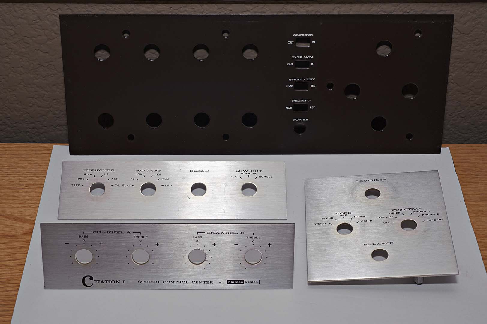
The face plate is held in place with 4 hex shaped stand off pieces and machine screws. Remove the 4 screws from inside the chassis and the faceplate comes right off. Once you have the large plate off, and it's heavy by the way, you can then detach the 3 separate silver plates from the heavy, brown colored back plate. Set these aside in a safe place for later cleaning and polishing. Despite all the hard work spent on the inside (where it counts), these 4 plates and the knobs are the only thing most people will ever see.
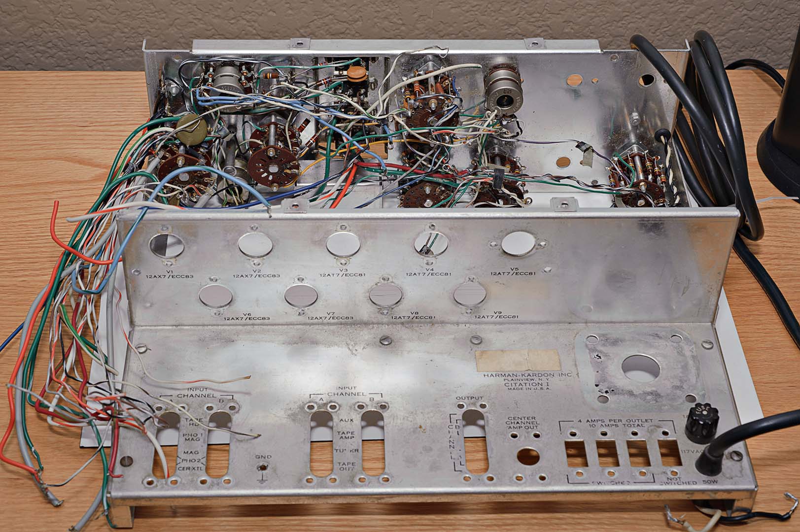
Finally, we get to the switches. There's a lot of wire there. It's going to be really time consuming to replace all that. Be very, very careful with the switches. They are old and cannot be replaced, except by cannibalizing another Citation. The picture on the left shows the chassis without the tube sockets and with 3 of the switches removed (Roll Off, Turnover, and one Treble switch). The right photo shows the front of the unit with the faceplate removed.

The switches are set aside for safe keeping. I will be replacing all the parts on those as well. While removing all the switches and wiring from inside the unit I came upon one final oddity. The previous owner of this pre-amp had substituted different value resistors for the 47K ohm resistors that run from the mode switch to the Tape Mon slide switch. 22K ohm resistors were put in place of the original values.
The black flexible tubing that holds the 3 wires to the power-on switch is removed. I haven't decided whether or not to replace the wires inside the flexible tubing. But the flexible tubing itself must not be damaged as it is needed again during reassembly. Finally, the lamp assembly and its black and white wires is removed. Again, be careful with this as you cannot replace this part.
With all the individual components now removed the chassis itself can now be taken apart into its 4 metal components. At this point the metal needs a good cleaning and polishing. What to use? That's the subject of my next post.
Time Spent: ~3 to 4 hours.

No comments:
Post a Comment