The last post where I actually built something left off with completion of the terminal boards on page 16 of the manual. Right after that comes the mounting of the terminal boards to the "shield assembly". I'm going to skip that for now. The problem with this step is that once you assemble the terminal boards with the shield you don't have a good way to rest the completed assembly without risking bending the neatly assembled components on the boards. I'll come back to this when the terminal boards are mounted to the chassis on page 19.
Next comes the power supply assembly. That was assembled earlier as it was done using McShane parts with steps that would have deviated from the assembly manual. That allows us to skip forward to page 18 to begin the chassis assembly.
The chassis assembly starts with the mounting of the phono socket strips. OK. Another detour from the manual is required. In order to install the phono strips as directed in the manual I first have to rebuild the old stock strips. About time to get rid of those old things and upgrade to gold plated sockets.
With each of the strips you want to retain the old black bakelite strips and the black insulating wafer. The idea here is to remove the old corroded aluminum socket and replace it with a shiny new gold plated one.
Take a basic pliers or needlenose and carefully bend the end of one of the two aluminum side tabs up just enough so that side of the RCA socket will swing free of the bakelite strip. Be very careful not to damage the strip. It's really very easy to pull off the old sockets. It takes time, but it's really not very hard.. There are 6 strips in total and 5 of them contain 4 sockets that must be removed.
The next step is to enlarge the round holes on each strip just enough to accommodate the new socket. You want to make it just large enough so that the BACK assembly of the new socket fits through the hole. If you make the hole too big you have just ruined the strip and you'll be looking for some other materials to fashion a new strip.
It is also extremely important that you keep each hole centered at the same point. You do not want to enlarge the hole off-center. The RCA sockets are spaced tightly together and also sit very close to the chassis. It won't take much of a shift in the center points to make it difficult to fit interconnect cables to the RCA sockets.
This brings up a side point. I'm building my Citation to the original instructions. This means that I will be placing just as many RCA sockets into the chassis as designed into the original. But as many of you already know, the sockets are so closely spaced that only very slim interconnect cables can be used to hook up your peripherals. Now is the time to decide whether you want to reduce the number of sockets in order to accommodate fatter interconnects. If you want to follow this path you will probably have to create your own mounting strips. I'm not sure that you can redesign the original bakelite strips for 3 sockets.
But I'm not doing that so let's get back to the task at hand. That task is to enlarge the oval shaped holes in the strips to accept the new round sockets. To do this I use a Dremel tool. I connect a small conical grinding stone to the drill. I then simply hold the strip in one hand while I press the drill into the original oval hole. I take care when enlarging the hole and proceed slowly. I drill a bit, keeping the grinding stone centered so as not to enlarge the hole off-center. Then I stop and try out a new socket in the hold to see if it fits. Then back to grinding. I alternate sides of the strip that I grind on (front and back) as the grinding stone is conical. I want the sides of the hole to be perpendicular rather than slanted.
Just keept doing this back and forth, grind then fit, grind some more then fit, until the socket just barely fits. Trust me, it doesn't take too much grinding to make the hole too big. When you have one hole finished go on the next.
When all the holes were drilled I then mounted the sockets. I carefully aligned all the grounding tabs to the same side. Here is a photo of the finished strips. Four of the strips have the insulating wafer in place. One strip on the right is shown without the insulating wafer and another one (also on the right) shows the back side of the strip without the wafer in place.
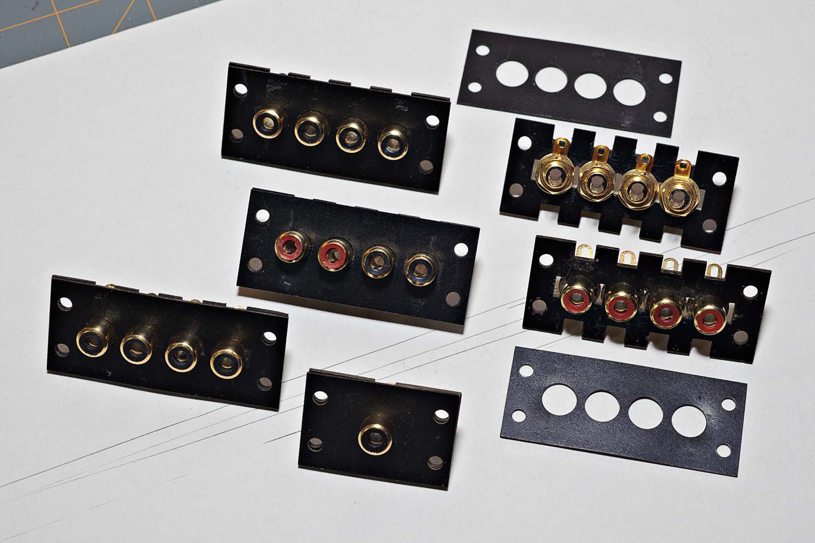
They look pretty nice at this point, and certainly are a major improvement over the stock RCA sockets (look at one of the previous posts for a "before" look). If you look at the strips without the insulating wafer you can really see just how close the fit is. And this brings up some final bits of instruction regarding this assembly.
Pay attention to the two strips without the insulating wafers. Look at the lower strip with red inserts. You can see the back side of the strip and you should be able to tell that the retaining washers are actually touching. This is no big deal for most of the strips as the ground tabs on that strip will be wired together using a short piece of wire.
However, the strips used for the phono sockets only have the ground tabs on two of the sockets wired together. The other two, I believe the Phono 1 and Tape HD sockets, are not grounded together. With such a tight fit how do you deal with this?
My method of dealing with this was to use a small file from my scale modeling hobby to file away the sides of the washers on those sockets that would not have their grounding tabs strapped together. If you look closely at the strip on the upper right showing the backside you can see the results of filing down the washers.
Another comment on the assembly is that I found it very hard to tighten the sockets while keeping the grounding lugs all parallel, not to mention keeping my filed washer sides oriented properly. There is nothing to grab onto when tightening the nut. You have to hold the socket on the front side with your fingers, as using a pliers would gouge the surface. At the same time you have to hold the grounding lug in place. If you don't it will rotate as you tighten the nut. Tightening the sockets was not easy.
After all the sockets were completed I decided to test an interconnect cable on one. Everything seemed fine as I plugged it in. Then I rotated the cable. Rats! The backside of the socket turned, including the grounding lugs. Apparently they weren't tight enough. Alright, I guess I just need to see if I can tighten them a little better. I finally got them to the point that they seemed tight enough. My fingers were pretty sore after completing all of the sockets. And there will always be a nagging question of whether they really are tight enough.
I'll leave you with one question. Do you think it matters which side you orient the grounding tabs on? Think about that before my next post.
Total time spent: ~3 hours.

No comments:
Post a Comment