Tuesday, October 27, 2009

Citation I Refurb - Chassis Wiring Continued

Yesterday's post left off at the top of page 19.  Let's pick it up from there, which begins with the wiring of the phono sockets, newly upgraded to gold plate.

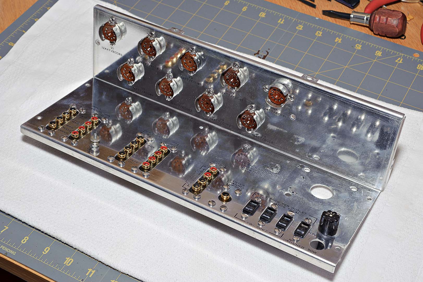
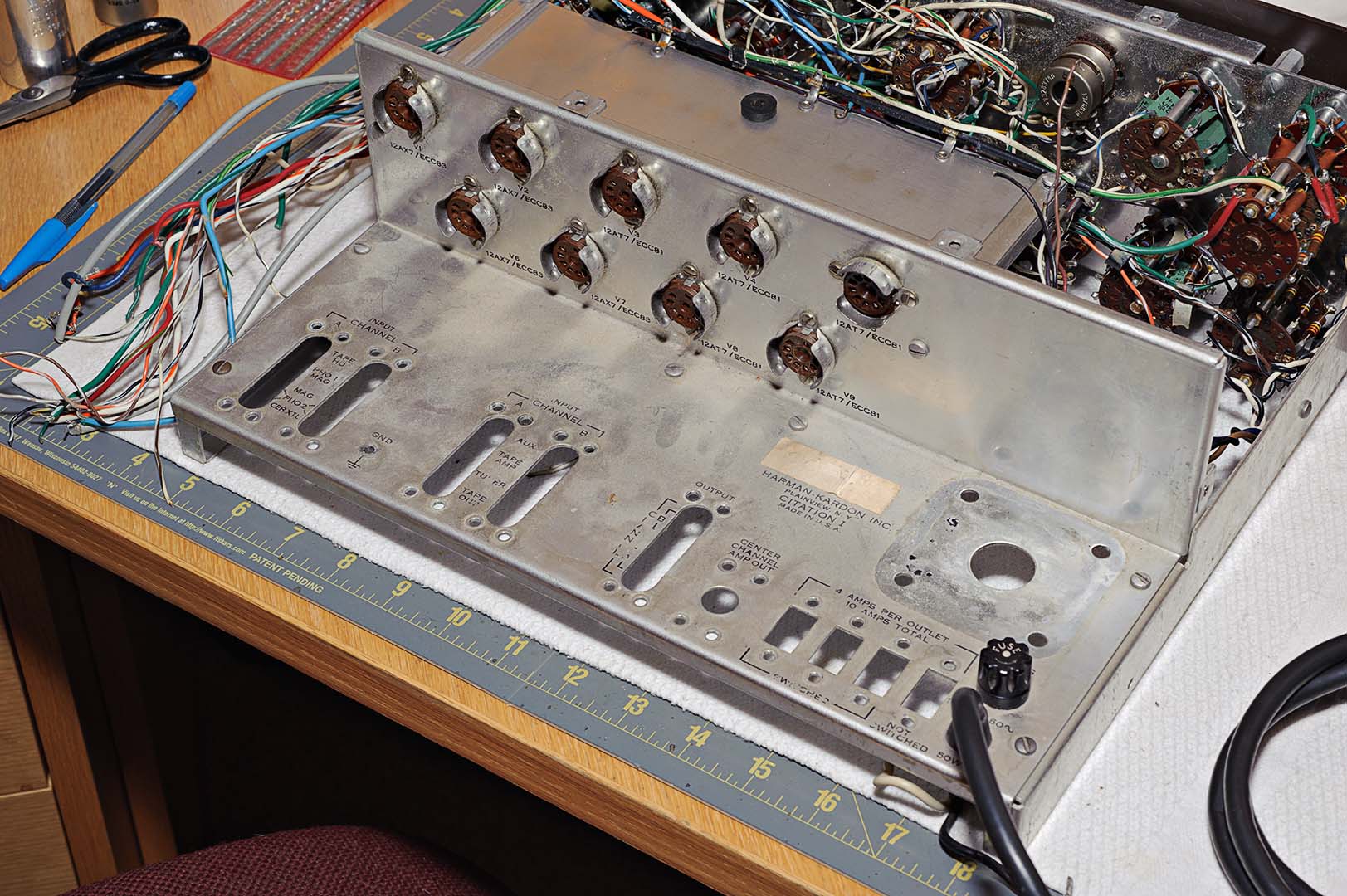
But first, let's pause here and go back two posts to a question I posed then.  Does it matter which side you position the ground lugs on when assembling the new phono strips?  Like a lot of things in life the answer is "it depends".  If you use RCA phono sockets that all have the same color insert then the answer is "No".  If you really don't care how neat your wiring job is the answer is also "no".  However, if you're using color keyed phono socket inserts like I am and you care about neatness then the answer is "Yes".  Here's a photo repeated from yesterday's post showing the chassis after the mounting of the RCA strips.


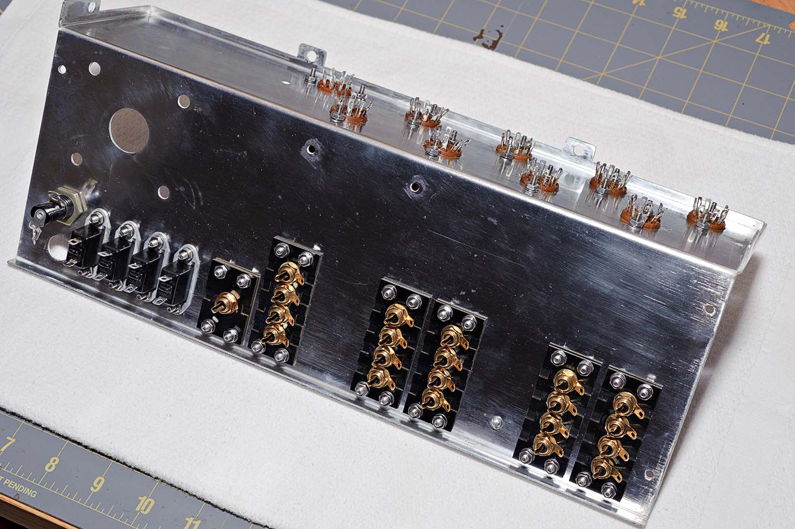
See how I have mounted the strips with the grounding lugs all pointed the same way?  This is wrong!  Unfortunately, I didn't catch my error in time.  I proceeded as indicated in the manual and completed the wiring of phono sockets.  When finished I looked at my work and then thought about how all the other wires that connected to the phono sockets were going to be arranged (or "dressed" as seems to be the proper term) in later stages of assembly.

See the two wide sections of bare chassis that run between the parallel strips of phono sockets.  Those bare areas are where you want to run the wires to the sockets.  So what you really want is to mount the phono strips such that the ground lugs are located next to the open chassis areas.  If you do like I did in the upper photo the wires will have to be dressed over the top of the sockets to reach the ground lugs.  Now look at the following photo.


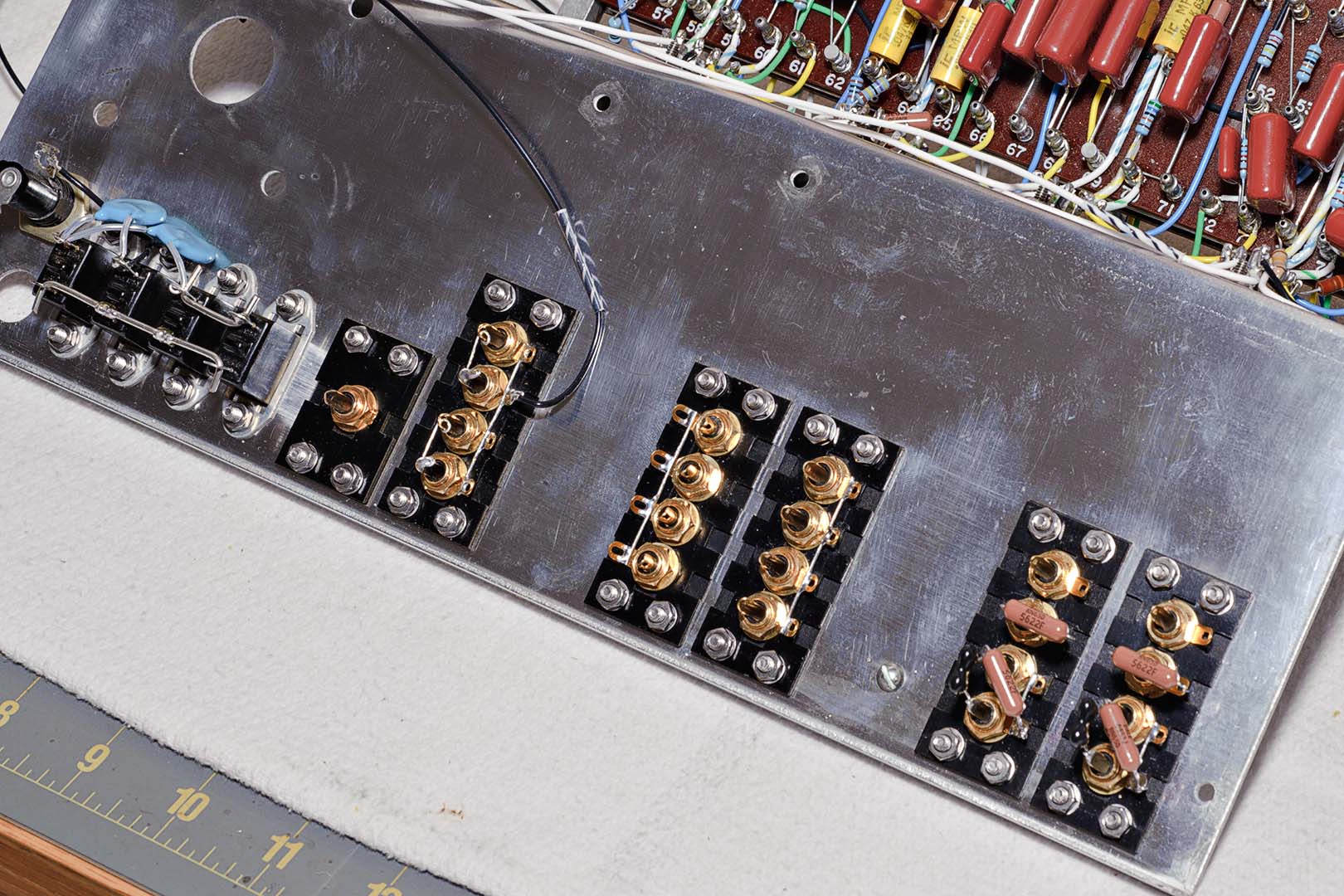
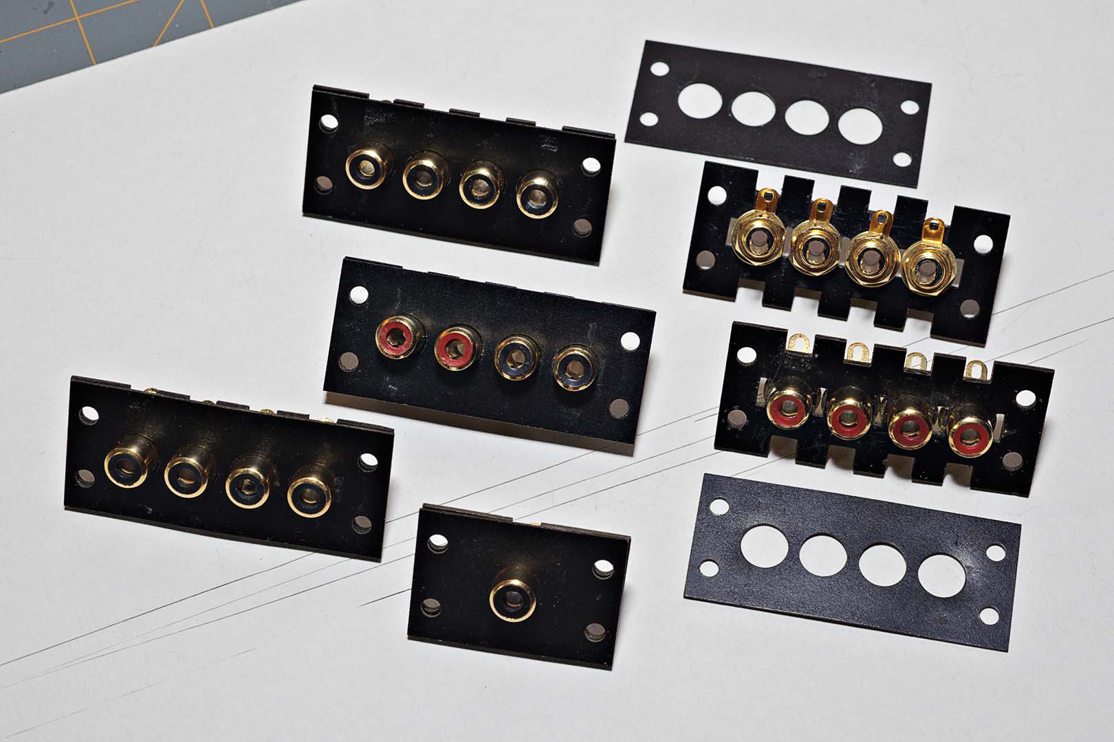
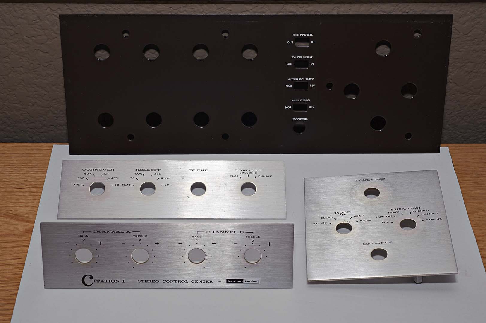
This is the arrangement that I ended up with.  See how I flipped around one of the strips, the fourth strip from the right?  I couldn't do that with the second strip from the right because 1) it was already wired and 2) this is one of the strips where I filed down the retaining washers so the grounds wouldn't touch.  Even if I desoldered the components I would still have had to remove the individual sockets themselves and remount them.  After the finger torture I went through to assemble them in the first place I was not about to disassemble and reassemble them again.  Similary, the last strip of four on the left cannot be flipped around either.  This strip has two red and two black inserts.  Flipping the strip around will make the red inserts the A channel and black will be B.

I corrected the orientation of the one strip I could change and left it at that.  If this is the worst mistake I make in the assembly of the unit I will have done an alright job.  But this does make a point.  Think out your work carefully.  And if you are using replacement parts with different geometrys than the originals then think ahead to issues that may arise.

The rest of the steps on page 19 were completed in sequence.  One item of note is the substitution of the original dual section triple lead 0.01 μF, 1400V capacitor.  From on-line discussions with members of The Citation Sound forum, particularly Paul Wolfe, I learned that this was a "safety" capacitor.  Except that it really isn't a true safety capacitor.  I replaced the stock cap with two X1/Y1 0.01 μF safety capacitors from JustRadios.com.  This safety cap has been tested to withstand 2500V AC for one minute.  Convenience outlet CO4 was used as the common tie point.  JustRadios.com has a good article on safety capacitors, the different types, and their uses.  Highly recommended reading for those restoring old vintage equipment.

The last step on page 19 is the attachment of the terminal board assembly to the chassis.  The terminal board assembly is described on page 16 of the manual.  If you recall from a couple posts back I did not assemble the terminal boards at that time due to the fact that I saw no way to store the assembly without bending some of the wired components.  So back to page 16 to complete the terminal board shield assembly and then back to page 19 to attach it to the chassis.

With the terminal board assembly now attached to the chassis the next steps are to connect all the wires from the terminal boards to the tube sockets.  The steps for this are laid out on pages 20 and 21, and a bit on page 22.  There are a lot of steps on these two pages, but not really much to comment on.  Well, I do actually have a couple comments at this point.

The first is that if you choose to use 20 gauge stranded wiring like I did you will have to be very careful when attaching the wires.  As I've already described way, way back I found this wire hard to work with for delicate wiring situations like the tube sockets.  Once you tin the ends, and you must do this, the wire becomes very stiff.  On top of that the pin lugs do not have very large holes.  For those pins that have multiple wires attached the size of the wire makes it a very tight squeeze.  But I took care and completed this wiring stage without incident.

My second comment is a general one regarding exposure of bare wire.  Whenever possible I am using clear Teflon tubing as sleeving to cover lengths of exposed wire.  For example, in the wiring of the tube sockets there are resistors running between the board and the sockets.  I use Teflon sleeving to insulate the longer resistor leads.  Likewise, I used Teflon to cover the leads of the X1/Y1 safety caps described previously.  The one big exception is that I did not use any sleeving on the components mounted entirely on the terminal boards.

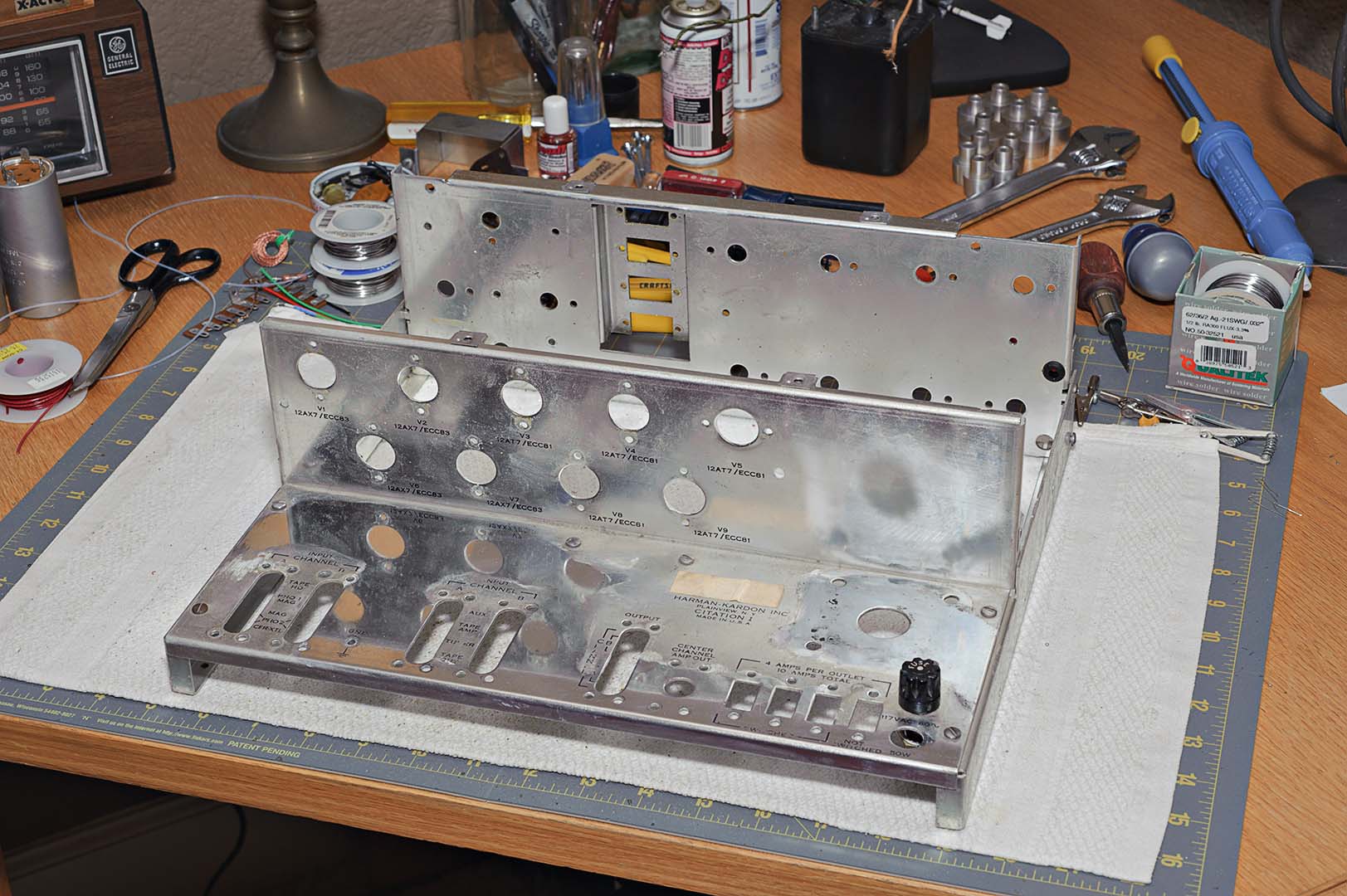
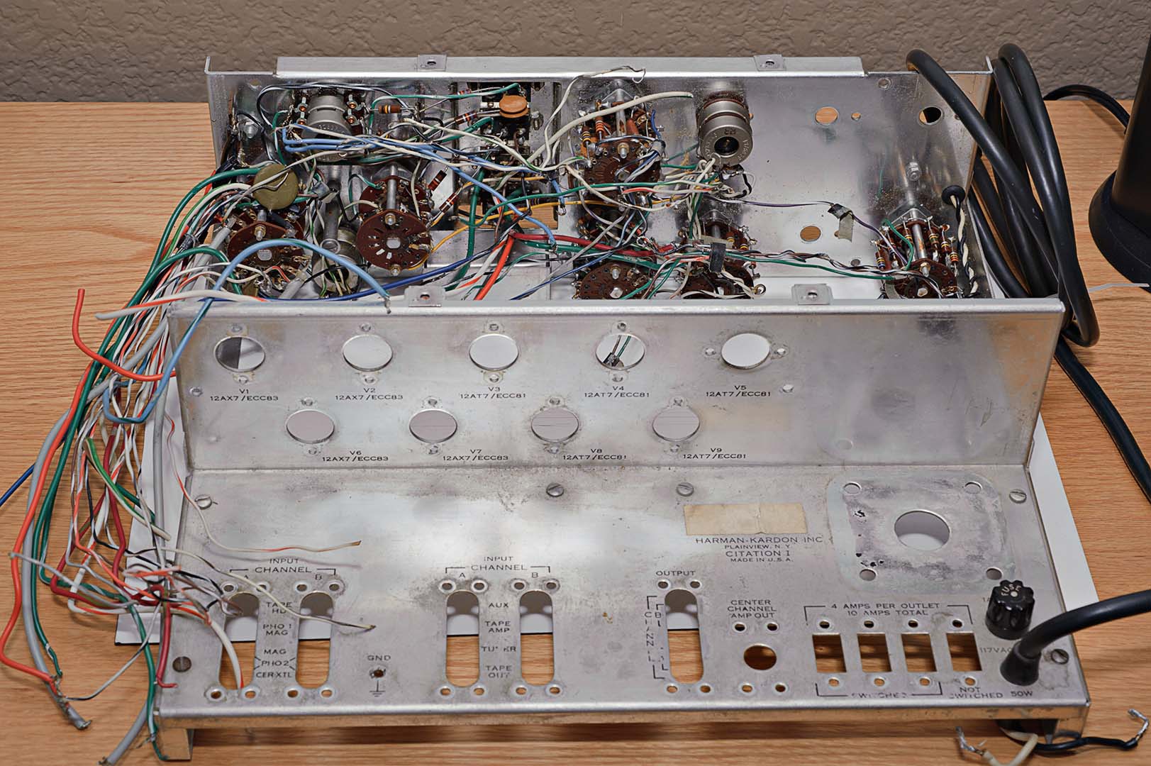
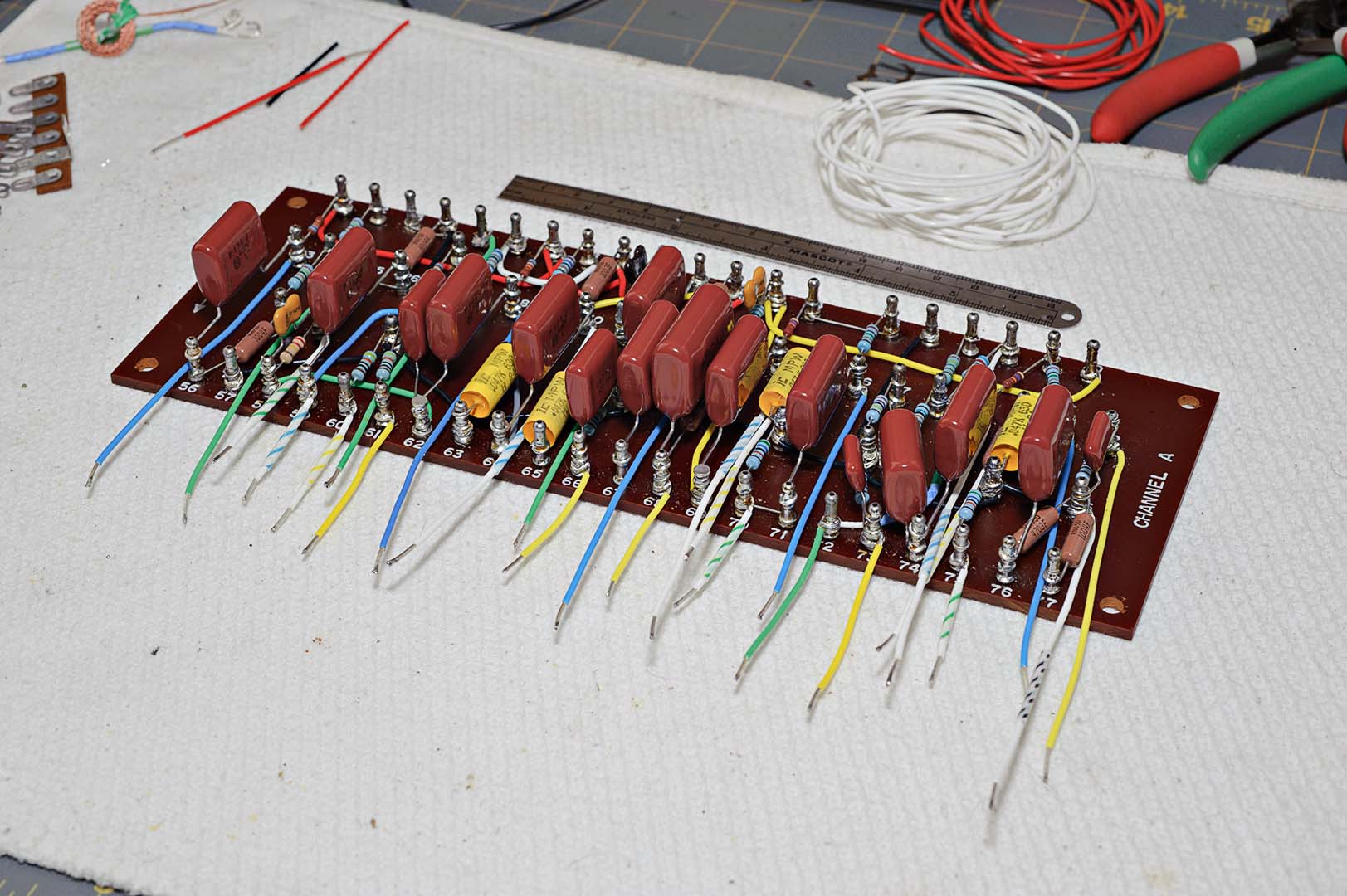
After completion of the tube socket wiring I was left with the chassis as depicted in the photo below.


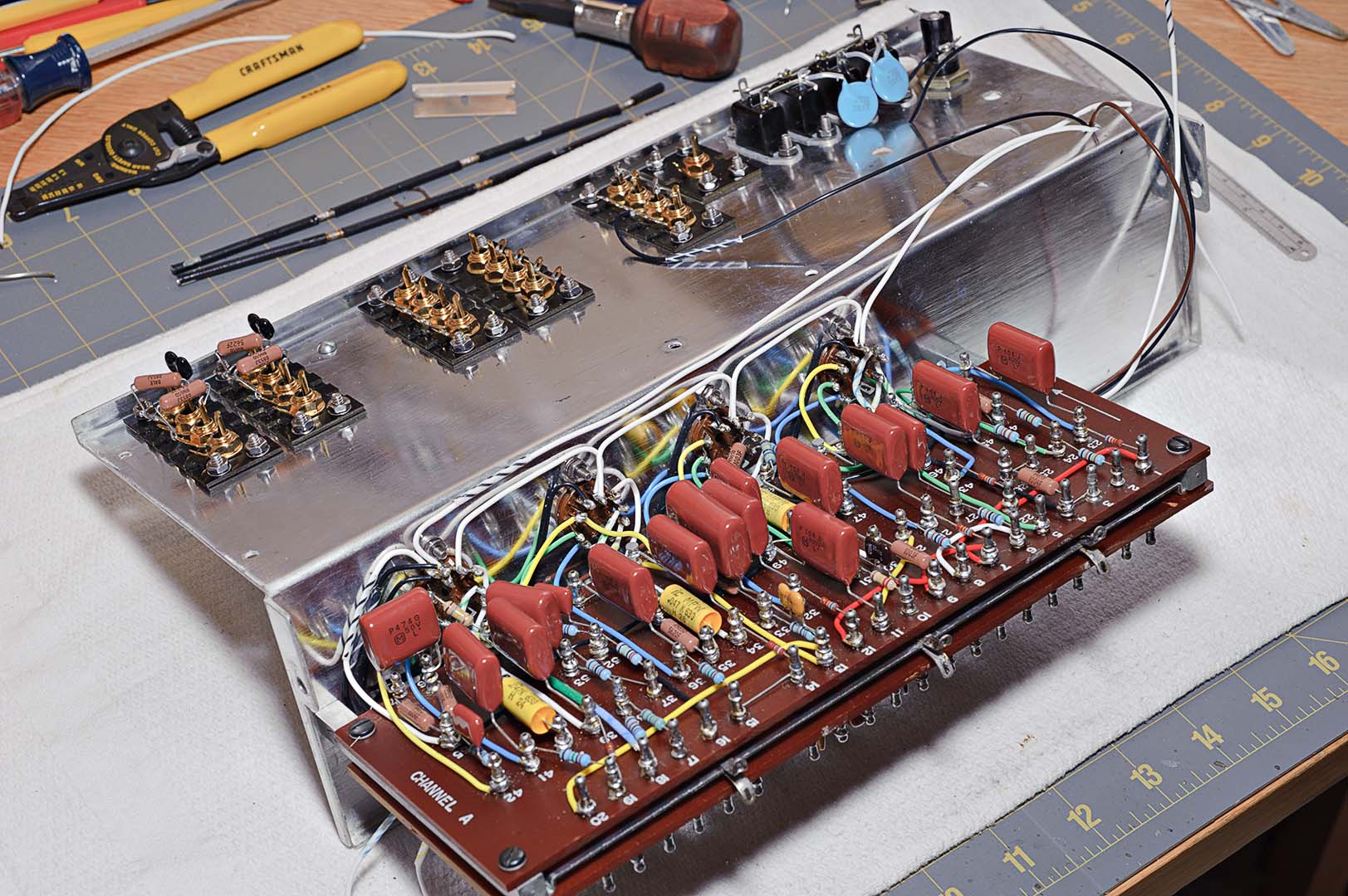
Let's power through one more page of assembly instructions before ending this post.  Continuing with the steps on page 22 I now attached the black flexible metal tubing to the edge of the terminal boards.  You can see the black tubing lengths sitting on the desk above the chassis in the previous photo.

Shielded wire was prepared, attached to, and then run along the terminal board.  Next, long lengths of purple, gray, and red wire were attached and dressed along the outside of the boards.  These wires were then dressed together with the black, white, white/black, and brown wires from the early tube socket wiring described in yesterday's post.  I'll make a note here that I am not using black tape to neatly bundle wires in my project.  Instead, keeping up with modern technology, small black cable ties are being used whenever black tape is called out in the instructions.

Short lengths of the same purple, gray, and red colors were used to connect lugs between the A and B boards.  Long lengths of wire were then prepped and run through the flexible black tubing.

That's it.  I'm now on the top of page 23 and will stop for the night.  The next section of the manual is to tackle the switch wiring.  We're going to have to take another detour here from the instructions, but more on that in the next post.

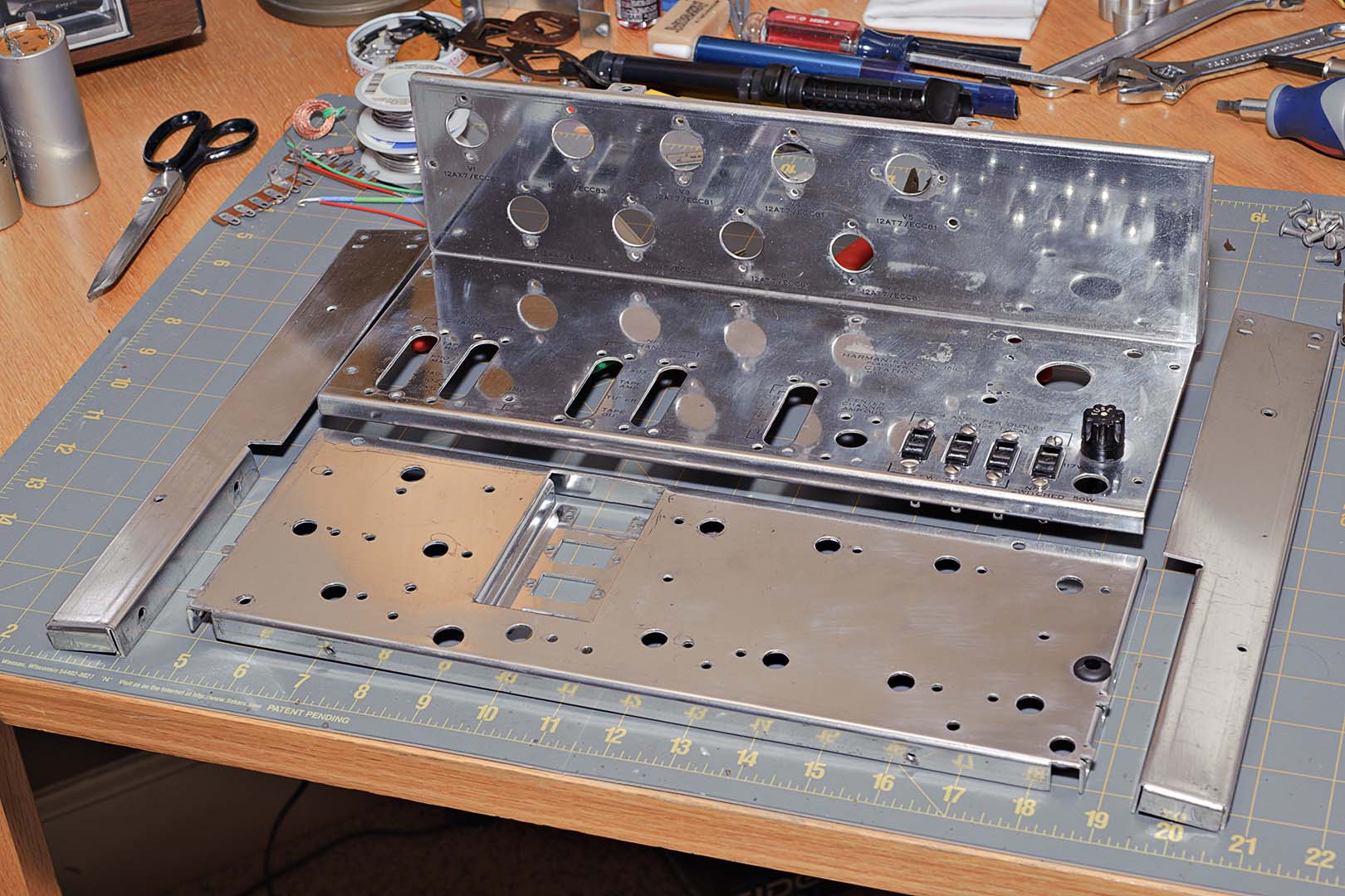
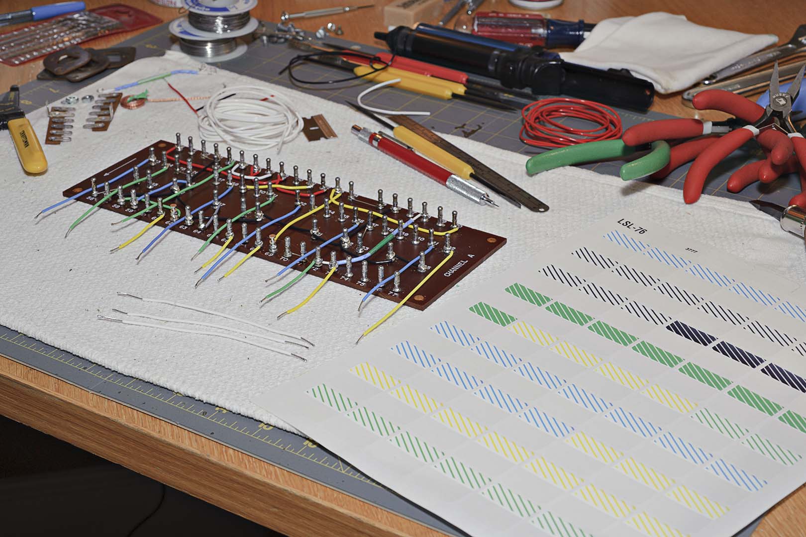
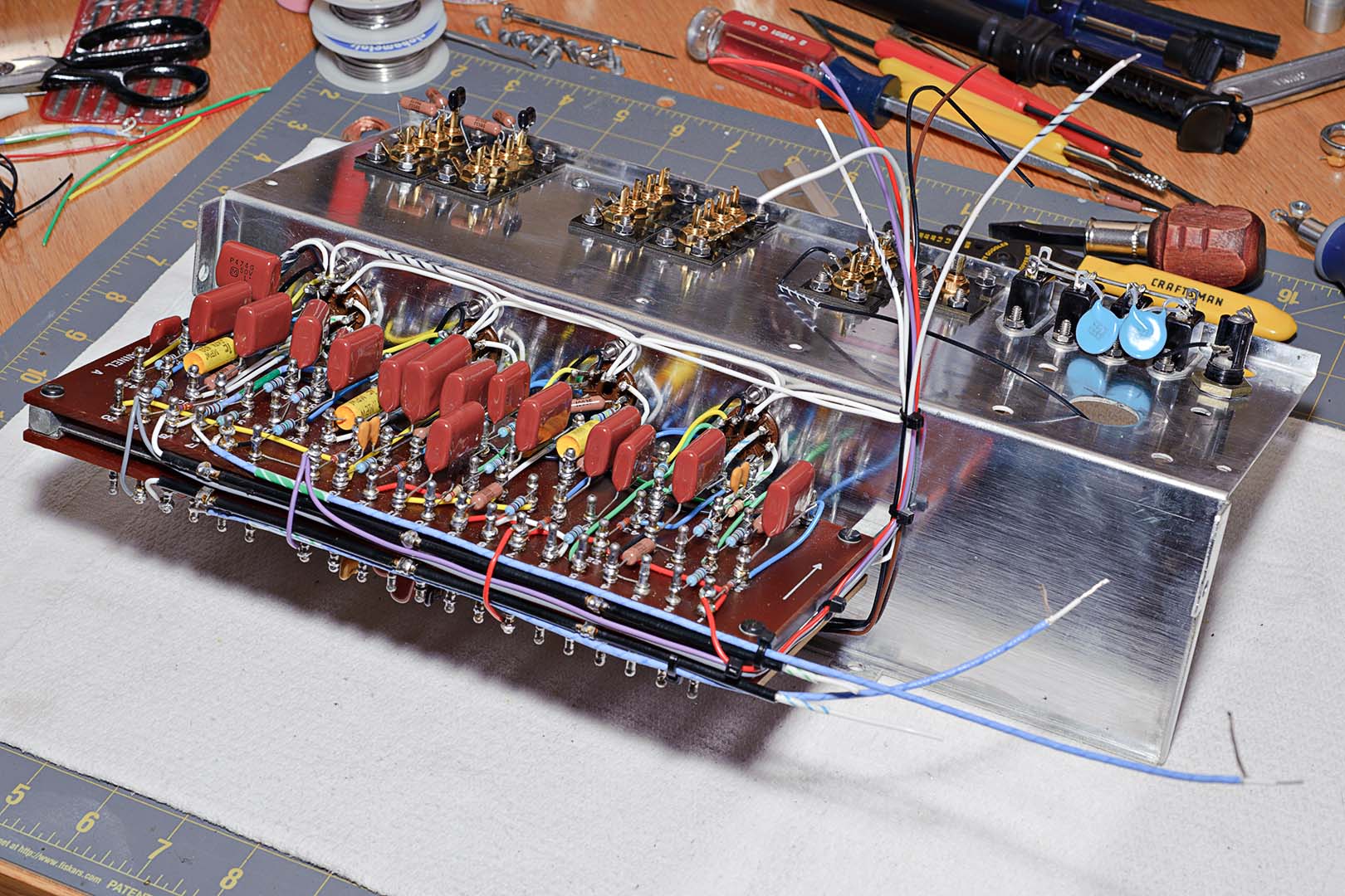
As I end this posting, let's take a look at the work to this point.  Here's a photo.  It's beginning to look very nice, I think!


Total Time Spent:  ~5 hours.

Citation I Refurb - Beginning the Chassis Assembly

The last post described the upgrading of the RCA sockets from the old stock aluminum type (fairly well oxidized by now in most examples) to new gold plated sockets.  Now that we've made the new RCA strips we can start the chassis assembly.  Let's start with a refresher photo of the stripped and polished chassis from an earlier post.


Beginning on page 18 of the manual, the first steps are pretty easy.  Using the large L-shaped chassis section, the tube sockets, RCA socket strips, convenience outlets, and fuse holder are installed.  In the photo above you can see that the convenience sockets and fuse were installed out of order according to the instructions.  Of course, I never took the fuse holder out when I took the chassis apart.  Also remember that I am using almost entirely new binding head machine screws, lockwashers, and nuts purchased from http://www.aaronsmachinescrews.com/.  I purchased both the #6-32 screws used predominantly in the assembly of the unit and #4-40 screws for the tube sockets.

After completion of the five steps under Chassis Assembly I had what is shown in the following two photos;  the first is the top side and the second is the underside.  You can tell from the photos that I am using black socket inserts for the A channel and red inserts for the B channel (Red is Right).


After the above steps had been completed I started on the chassis wiring.  The chassis wiring begins with the wiring of the tube sockets.  Black wire is used to tie together Pins 4 on all the tubes, brown wire is used to tie together Pins 5 on Channel B, and white wire is used  to tie together Pins 5 on Channel A.  Unfortunately, I forgot to take a photo after this wiring step was completed.

So here's a question I had as I assembled not only this Citation I, but also my previous Citation II amps.  Do the wire colors used in electronics have standardized meanings?  I finally took the time to look it up.  For the most part the answer is yes.  Here are some standard color uses.

Black = Grounds and returns
Brown = Heaters or Filament
Red = High Voltage (Power Supply B+)
Orange = Screen Grid
Yellow = Cathode
Green = Control Grid
Blue = Plate
Violet = Power Supply negative
Gray = AC power lines (sometimes Black/White is used)
White = Bias, Miscellaneous, above grounds, AGC

These color usages were obtained from this handy PDF file I found on-line - http://www.tentlabs.com/InfoSupport/page35/files/wiringcolours.pdf.  This file contains wiring colors for transformers as well.  So, how do these standard colors match up to the pinouts for the tubes used in the Citation I; 12AX7 and 12AT7?  These tubes are dual section triodes and have identical pinouts that are as follows:

Plate = Pins 1, 6
Grid = Pins 2, 7
Cathode = Pins 3, 8
Heater = Pins 4, 5
Pin 9 is not used in the Citation I

So in this case the brown to pins 5 make sense.  But I'm not sure about the usage of black on pins 4 or white on the A channel pins 5.  When we get to the hook up of the remaining pins in a later section we see that Harman Kardon followed the blue, yellow, green standard.

That's all I'm going to write about this time.  Where did we leave off?  We have just completed Pictorial 4, Figure B and are in the top half of page 19 about to start on Pictorial 4, Figure C.

Total Time Spent: ~1 hour for the above work.

Sunday, October 25, 2009

Citation I Refurb - Upgrading the RCA Plugs

For those wondering just how much it costs to rebuild a Citation I the previous post may have been interesting.  But enough of the soft stuff.  It's time to get back to building.  So where are we?  Let's see...

The last post where I actually built something left off with completion of the terminal boards on page 16 of the manual.  Right after that comes the mounting of the terminal boards to the "shield assembly".  I'm going to skip that for now.  The problem with this step is that once you assemble the terminal boards with the shield you don't have a good way to rest the completed assembly without risking bending the neatly assembled components on the boards.  I'll come back to this when the terminal boards are mounted to the chassis on page 19.

Next comes the power supply assembly.  That was assembled earlier as it was done using McShane parts with steps that would have deviated from the assembly manual.  That allows us to skip forward to page 18 to begin the chassis assembly.

The chassis assembly starts with the mounting of the phono socket strips.  OK.  Another detour from the manual is required.  In order to install the phono strips as directed in the manual I first have to rebuild the old stock strips.  About time to get rid of those old things and upgrade to gold plated sockets.

With each of the strips you want to retain the old black bakelite strips and the black insulating wafer.  The idea here is to remove the old corroded aluminum socket and replace it with a shiny new gold plated one.

Take a basic pliers or needlenose and carefully bend the end of one of the two aluminum side tabs up just enough so that side of the RCA socket will swing free of the bakelite strip.  Be very careful not to damage the strip.  It's really very easy to pull off the old sockets.  It takes time, but it's really not very hard..  There are 6 strips in total and 5 of them contain 4 sockets that must be removed.

The next step is to enlarge the round holes on each strip just enough to accommodate the new socket.  You want to make it just large enough so that the BACK assembly of the new socket fits through the hole.  If you make the hole too big you have just ruined the strip and you'll be looking for some other materials to fashion a new strip.

It is also extremely important that you keep each hole centered at the same point.  You do not want to enlarge the hole off-center.  The RCA sockets are spaced tightly together and also sit very close to the chassis.  It won't take much of a shift in the center points to make it difficult to fit interconnect cables to the RCA sockets.

This brings up a side point.  I'm building my Citation to the original instructions.  This means that I will be placing just as many RCA sockets into the chassis as designed into the original.  But as many of you already know, the sockets are so closely spaced that only very slim interconnect cables can be used to hook up your peripherals.  Now is the time to decide whether you want to reduce the number of sockets in order to accommodate fatter interconnects.  If you want to follow this path you will probably have to create your own mounting strips.  I'm not sure that you can redesign the original bakelite strips for 3 sockets.

But I'm not doing that so let's get back to the task at hand.  That task is to enlarge the oval shaped holes in the strips to accept the new round sockets.  To do this I use a Dremel tool.  I connect a small conical grinding stone to the drill.  I then simply hold the strip in one hand while I press the drill into the original oval hole.  I take care when enlarging the hole and proceed slowly.  I drill a bit, keeping the grinding stone centered so as not to enlarge the hole off-center.  Then I stop and try out a new socket in the hold to see if it fits.  Then back to grinding.  I alternate sides of the strip that I grind on (front and back) as the grinding stone is conical.  I want the sides of the hole to be perpendicular rather than slanted.

Just keept doing this back and forth, grind then fit, grind some more then fit, until the socket just barely fits.  Trust me, it doesn't take too much grinding to make the hole too big.  When you have one hole finished go on the next.

When all the holes were drilled I then mounted the sockets.  I carefully aligned all the grounding tabs to the same side.  Here is a photo of the finished strips.  Four of the strips have the insulating wafer in place.  One strip on the right is shown without the insulating wafer and another one (also on the right) shows the back side of the strip without the wafer in place.


They look pretty nice at this point, and certainly are a major improvement over the stock RCA sockets (look at one of the previous posts for a "before" look).  If you look at the strips without the insulating wafer you can really see just how close the fit is.  And this brings up some final bits of instruction regarding this assembly.

Pay attention to the two strips without the insulating wafers.  Look at the lower strip with red inserts.  You can see the back side of the strip and you should be able to tell that the retaining washers are actually touching.  This is no big deal for most of the strips as the ground tabs on that strip will be wired together using a short piece of wire.

However, the strips used for the phono sockets only have the ground tabs on two of the sockets wired together.  The other two, I believe the Phono 1 and Tape HD sockets, are not grounded together.  With such a tight fit how do you deal with this?

My method of dealing with this was to use a small file from my scale modeling hobby to file away the sides of the washers on those sockets that would not have their grounding tabs strapped together.  If you look closely at the strip on the upper right showing the backside you can see the results of filing down the washers.

Another comment on the assembly is that I found it very hard to tighten the sockets while keeping the grounding lugs all parallel, not to mention keeping my filed washer sides oriented properly.  There is nothing to grab onto when tightening the nut.  You have to hold the socket on the front side with your fingers, as using a pliers would gouge the surface.  At the same time you have to hold the grounding lug in place.  If you don't it will rotate as you tighten the nut.  Tightening the sockets was not easy.

After all the sockets were completed I decided to test an interconnect cable on one.  Everything seemed fine as I plugged it in.  Then I rotated the cable.  Rats!  The backside of the socket turned, including the grounding lugs.  Apparently they weren't tight enough.  Alright, I guess I just need to see if I can tighten them a little better.  I finally got them to the point that they seemed tight enough.  My fingers were pretty sore after completing all of the sockets.  And there will always be a nagging question of whether they really are tight enough.

I'll leave you with one question.  Do you think it matters which side you orient the grounding tabs on?  Think about that before my next post.

Total time spent:  ~3 hours.

Sunday, October 18, 2009

Citation I Refurb - Rounding Up the Parts

I've been saying I'll do a post about the rounding up of all the parts.  Well, here it is.  There's no pictures in this post so I hope I can keep your attention.

There is a lot of work involved in finding a source for all the Citation parts.  There is no one place you can go to get everything.  You would think Mouser or Digi-Key would have everything.  While they may have correct values for most parts they don't always have the part in the right material or physical size.

For example, say you want a 0.0075 µF capacitor for a switch.  Let's say you want polypropylene film and foil.  Because it's for a switch it also really needs to be no more than 10mm wide.  If you want a polyester cap you may not have any problem.  But who wants polyester?  First off, you probably won't find a 0.0075 µF cap (I didn't).  So now you have to choose between 0.0068 µF or 0.0082 µF.  One vendor I tried had one value and not the other, another had the opposite.  You may not find polypropylene film and you have to settle for metallized polypropylene.  The point is that it takes a lot of searching to find everything.

So what was my strategy for securing all the parts?  When I first started this project my aim was to buy the best types and brands of components I could find.  But just what is the best?  Should I buy carbon comp, carbon film, or metal film resistors?  For filter caps should I get polypropylene film or metallized polypropylene or something else?  How about small value caps?  Mica or polyester?

After trying to come up with all the "right" answers I gave up.  It was too much work and getting me nowhere.  In the end I based my decisions on three ideas.

First, Jim McShane has already done a lot of the experimentation.  Here's a quote from his Citation site (Jim McShane - Citation Amp and Tubes).

"A total recap of a Citation I is a very difficult, time consuming, expensive task. There are 102 caps in a Citation I, not counting the power supply cans! I've also found that many of the caps you work so hard to replace have no effect on the sound quality. Many are even switched out of the circuit in normal use! I don't recommend you do a total recap unless you're a glutton for punishment...  So what can you do? Well, I've tried to isolate the key circuitry, and focus attention on the caps that make the biggest difference in your preamp. The result is a pair of affordable, high quality kits of caps for the Citation I.  All the caps in both kits (except micas) are film and foil, and most have oxygen free copper leads. And they sound great!"

OK, first solution... let's use Jim's kits as a starting point.  But apparently I'm a glutton for punishment according to Jim as I'll be going a bit further than the kits.

The second idea takes his statement above (that many of the cap replacements have no effect on sound quality) and extends it with an opinion he told me in a private e-mail.  Basically, he said, just about any cap you buy out there today is going to be better than what was in the original kit.  What that means to me is that I'm not going to sweat it.  Jim likes film and foil and I'll try and stick with it.  But if I can't find a film and foil cap I'm not going to worry at all over buying something else like metallized polypropylene.  But no polyester!

Lastly, I'm using Jim's opinion on resistor replacement (because it matches my own thoughts).  I have heard opinions by some to use carbon comps in the Citation I.  But carbon comps are noisier than other types.  In tube equipment you have a higher level of inherent noise to begin with.  Don't you want to stay as quiet as possible in the pre-amp stage?  So why add to the problem by using carbon comps?  Jim was emphatic in his opinion to keep the pre-amp as quiet as possible by using metal or carbon film resistors and to avoid carbon comps.

I suspect that carbon comps are used by some to impart some of that warm tube sound.  Given that the Citation II amp is known to give a dry and "correct" sound with less of the usual tube warmth this idea may have merit.  But I'm with Jim on this one.  I'll be using metal film resistors primarily.

I also need to order various other pieces of hardware.  I'll need to order shielded wire, gold plated RCA jacks, some convenience outlets, etc.  It all adds up.  Some of you reading this may no doubt say that I could get some of these parts cheaper than from Jim.  True, a bit cheaper.  But Jim has done the legwork in many cases and I can trust that I'm buying the right component.  Jim's also an invaluable source of Citation know-how.  I feel it's only right to give him as much of my business as possible.

Now that I've decided on some "rules" let's get to the business of ordering parts.  Here's the first easy order.

Jim McShane Power Supply Kit - $107
Jim McShane Kit 1-CP (Phono kit) - $75
Jim McShane Kit 1-CL (Line kit) - $45

Jim also offered me an "Extras Kit".  He doesn't have this kit on his website.  At least not yet.  It contains extra caps and resistors to improve the "phono stage, NFB loops, and key resistors" that I suppose are the result of Jim's on-going experimentation with improving the sound of the Citation I.

Jim McShane Extras kit - $67
10 pairs of gold plated phono jacks - $6.50/pair
3 Kulka convenience outlets - $7

Round One Total:  $366

Next order of business is to total up all the parts in Jim's kits and compare to the inventory of parts for a Citation I.  The best source for this is the Citation I Assembly Manual.  The manual lists all the individual resistors and capacitors that shipped as loose components.  In addition, the manual has a separate list of all the parts that come pre-assembled on the switches.  This is useful information because you know that all of these switch components are going to be size restricted.

In order to determine all the parts that I still needed I created a spreadsheet to list out all components (by value) and their quantity.  I added a second column for the number of parts that came from the Jim McShane kits.  This not only gave me a quick way to calculate what was still needed, but it also allowed me to see what parts I could get from Jim.  For example, if I needed 10 resistors of X ohms and Jim supplied me with a total of 4 in his kits then I knew I could order the remaining 6 from his also.  For the rest I would be on my own.

The rest of the parts were ordered from various sources, mainly Mouser.  But I also ordered some parts from Digi-Key and Just Radios.  I used Just Radios to order two X1/Y1 safety capacitors.  These caps cost 60 cents each.  But Just Radios has a minimum purchase of $15.  So I ended up ordering small value mica capacitors from them that I can use in my next project.

Most of the parts from Mouser are Xicon brand resistors and caps.  But there are some Vishay, KOA, and CDE parts scattered about.  All the resistors ordered were metal film with the 1/2 watt ones being 1% tolerance.  The Vishay 1 watt 68K resistors were 5%.

500V mica caps were ordered for everything under 1000 pF.  All the micas ordered from Mouser were CDE.

The larger cap values (0.001 µF to 0.022 µF) were a mix of polypropylene film or metallized PP film from Xicon, CDE, or Panasonic.  The Panasonic caps were obtained from Digi-Key and were out-of-production stock of polypropylene foil and film.

The cost of the turret staking tool and the turrets that I spoke about in a previous post is also included here.

Jim McShane Additional parts - $79
Mouser Parts #1 - $64
Mouser Parts #2 - $28
Digi-Key Parts - $5
JustRadios Parts - $1

Round Two Total:  $177

Next I needed shielded wire.  Where to get shielded wire?  The biggest problem with wire is not so much finding it.  Rather, the real problem is that almost everyone has minimum order sizes of 100 feet or more.  I ended up finding what looked to be a good alternative from a seller on eBay.

He sells wire in 25 foot quantities and had almost exactly what I was looking for.  22 gauge silver coated stranded inner core with a Teflon jacket.  Then a shield of silver coated braid.  The outer covering was Teflon tape.  Total diameter of the cable is approximately 0.085".  It's actually slightly thinner than the original shielded wire, which is about 0.106".  Cost for 25 feet of this wire is $13.  Not bad.  The problem, of course, is that the wire is all one color.  But I talked about this problem earlier and my solution; wire labels from ZipTape.com to be printed on a color laser - $20.

This project will use close to 25 ft. of shielded wire.  While I was at it I bought a couple extra coils of this wire for future projects.  I've only included the cost for one purchase here, however.

Round Three Total:  $33

Lastly, I think, are the replacement machine screws I purchased.  I didn't have to replace the screws, of course, but the original screws all look pretty ugly (oxidation, corrosion, etc).  Sure, they're mainly hidden from view so who cares?  But I'm going to all this effort to refurbish this old beauty so why not go all out?  I've got a good tip for anyone looking for replacement Citation I or II screws.  Aaron's Machine Screws.  Screws, nuts, and washers are all about $0.15/ea when ordered in minimum quantities of 100.

This gets expensive when ordering all the different sizes for a Citation project.  But these are all good quality and good looking screws.  In fact, orders of magnitude better than what you will likely find at your local hardware store.  They also sell black anodized binding head machine screws with slotted heads, a very good match for the original Citation II screws.  Order the "fine" size black anodized nuts and lockwashers to match and you're set to go.

I will only be using some of the screws for this project.  In fact, the most called for screw in the Citation I kit is the #6-32, 3/8" size.  You need 48 of these I believe.  So I have enough to replace screws on a second Citation as well.  I have far more than I will ever use of all the other sizes I ordered.  So you have to spend $115 if you're going to get all the correct sizes.  But you'll probably only use about $30 worth of screws, nuts, and lockwashers.

Round Four Total:  $115

Well that's it for parts.  I think I've covered everything.  There are some little odds and ends here and there that I bought locally.  Nothing major though and nothing that would make a dent in the overall cost.

Grand Total:  $691

Yikes!  That's actually the first time I totalled up the entire cost.  I can't say I'm surprised.  I knew I was getting up there.  That amount also does not include shipping costs.

Not included in these costs - I already had on hand many feet of variously colored Teflon coated stranded wire.  So for anyone repeating my project, you will need to buy wire in addition to everything else.

One last tip.  In Jim McShane's power supply kit are two 0.01 µF PP caps.  Coincidentally, there are two of this size called for in the assembly manual.  The problem is that Jim supplies these caps as additions to improve the phono qualities of the power supply.  So when I went through my spreadsheet to calculate out what I needed to buy it looked like I already had the 0.01 µF caps in the original schematic.

So now I find myself two caps short.  These caps cost about $0.20 each at Mouser, but that will also cost you $7 in shipping.  Not exactly cost efficient.  So I ordered more gold plated RCA jacks for my next project to make it worth the shipping charges.

Lesson learned:  Shipping costs can eat you up.  Be sure to order everything in as few shipments as possible.

Saturday, October 17, 2009

Citation I Refurb - Chassis Cleaning

In the last post I finished the tear down of the chassis. I had wanted to include the cleaning of the chassis as well, but the post was getting a bit long. It's a few days later now so let's "finish" it. (Bad pun) I also have this nagging feeling that there is an item that I wanted to be sure to include in this post, but I'm drawing a blank at present.

At the end of the last post I stated that the chassis has now ready to disassemble to its four individual pieces.  This is true, but before I did that I spent time deciding how I was going to handle the cleaning and possibly polishing of the metal.  I want to get rid of the oxidation of course, but I need to make sure I don't harm any of the lettering.

I didn't have a clue. I decided to try a general purpose metal cleaner.  Off to the supermarket.  I went to the aisle where they sell household silver and brass cleaners. Sitting on the shelf were a couple of all-purpose metal cleaning products. I chose a bottle called "Mr. Metal" with Tarnish Guard. The bottle claims to "Clean, shine, and protect all metal surfaces instantly. Just wipe on and wipe off.  Mr. Metal shines all metal objects from the finest sterling silver to the dullest auto wheels and marine hardware." Sounds good to me.

Back at home I then did what anyone would recommend.  Try it first on a small section that isn't visible.  I followed the instructions and...  Wow, this stuff works!  It's not exactly wipe on and wipe off.  But it's not bad.  You certainly don't have to use too much muscle to polish and buff.  OK, let's do the big test; try it on a section of chassis that contains lettering.

The chassis does not have perfect rear deck lettering.  There are some areas where the lettering has been partially worn away.  One example is around the convenience outlets.  This seems like a good test area.  If I lose a little more outlet lettering that's not a big deal.  So let's test...  Yes, no problem!  Mr. Metal restores a beautiful shine to the chassis and does not remove any lettering.  I continued on and polished a larger area.  Here is a photo of the partially polished rear deck.  Notice the difference between polished and unpolished areas.  Especially take note of reflections.  This is where it is most obvious.  If you go back to the previous blog post you can also compare an untouched chassis.  I'm not sure that the photos do it justice but this polish really works.


You'll also note that I have removed the power cord.  It would have been easier to leave it in, but it would have made the polishing process harder.  But I have kept the fuse holder in place.  I have removed this when working on my Citation II amplifiers but decided to leave it in this time.  Now the chassis can finally be broken down into the four individual pieces; the front panel, two side panels, and what I have been referring to as the rear deck.  And one last piece was removed as well.  The small rubber grommet for the wires of the lamp was cut away.  This piece, as is usual with these old grommets, was completely hardened and had to be cut off with a razor blade.

At this point there's not much to write about.  Mr. Metal is applied using "shop cloth rags" bought at Home Depot, using a bit of light rubbing and then removed.  The polish turns black as it reacts with the metal but it all comes off, leaving a bright shine.  Now, it's not perfect.  The chassis has some scratches that aren't removed by the polish as well as some deeply oxidized speckles here and there.  I suspect that those spots are areas where the oxidation has gone deep down into the metal.

Here are the four finished panels.  All in all I am very pleased with the results.  The question is going to be how long that nice shiny finish will last.  As I handle the polished parts I find that they show fingerprints very easily now.  So as I assemble everything over the next few weeks I am going to have to do a final cleaning.  I'm hoping that will just be a "wet wipe" with some Windex or something.


If you're following my posts carefully you may also notice a couple of things in this last photo.  First, notice that I have already installed a new grommet in the front plate.  I installed a 1/4" grommet and it really is too big for the hole.  But I was able to brute force it into the hole.  Good enough.  A 3/16" grommet would have fit better, but I would have had to run around to find one of that size.  Second, notice that I have already put in the new convenience outlets.  And third, you probably can't tell from this photo, but the machine screws holding in the convenience outlets are new.  I will be using new screws during reassembly.  More on that in my future parts posting.

So that's it with the tear down.  All done.  Time to build now, right?  Well... actually no.  The rotatary and slide switches all have to be cleaned up.  The rotary switches are especially going to be time consuming.

Time Spent:  ~3 hours

Monday, October 12, 2009

Citation I Refurb - Finishing the Chassis Teardown

At this point in the refurb we have completed the wiring of both terminal boards and have redone the power supply using the McShane kit.  I am using the original assembly manual and proceeding step by step.  A section is completed, checking off each step.  At the end of the section I go back and double check each step and check of the "Checked" column.  This puts us in the middle of page 18 of the manual.

The next section of the manual starts with the assembly of the chassis.  So I really can't go any further until I clean up the rest of the chassis.  Let's go back and look at my original high level plan.
  1. Completely disassemble the Citation I into its parts. Just like when the kit box was opened.
  2. Order all the replacement parts. This can happen in parallel with the first step.
  3. Clean all of the hardware as close to an "as new" state as possible.
  4. Assemble the Citation I according to the Harman Kardon assembly manual.
I never completed step 1, but instead started in on step 4 once I had the terminal boards extracted.  I'm glad I did that simply because it satisfied a bit of desire to start building rather than de-construct.  The time has come, however, to finish up the rest of the teardown process.  Step 2, the ordering of parts, has been completed (more on this in a later post).  Step 3 can't be completed until the teardown has been completed.

To begin the rest of the teardown I started with the rear deck of the chassis that contains the transformer, the convenience outlets, and the RCA jacks.  The transformer was removed earlier when the power supply bracket was removed.

The RCA jack strips were removed.  It is very important to keep these unless you want to fabricate your own RCA strips from scratch.  If you want to do this check out Sheldon Stokes' site at http://www.quadesl.com/.  He has a template available for download if you want to cut your own RCA mounting strips from a suitable blank such as GR-4 circuit board material.

Next I removed the convenience outlets.  Remember from an earlier post that 3 out of 4 of these outlets are chipped so I will be installing new Kulka outlets.  For now, I'm leaving in the fuse holder and the power cord.  Here's a photo of the work chassis at this point.


Continuing on, the next step is to remove the 9-pin sockets.  This is an easy task as all the wires have been removed.  The sockets are set aside for the assembly phase.  But before I set them aside I deposited a bit of Deox-IT Power Booster on each pin socket.  I tried to use a length of pipe cleaner with Deox-IT applied, as suggested by someone.  But the pipe cleaners I tried were simply too big to fit in the small pin holes.  And on top of that the fibers tore from the wire and remained in the socket.  So after trying this on one pin socket I gave up and simply brushed some Deox-IT into each hole.

If you recall, I broke one of the pin lugs off the V3 socket when removing the old wires.  I purchased a replacement for this one.  But imagine my surprise as I applied Deox-IT to each socket and found a missing pin lug on socket V5.  Now I know I did not break that pin off.  So this is one more example of the state of this amp.  It really does need a refurbishing.  I didn't want to beg my source for another socket so I went out to the garage and pirated a socket from one of my other units.  I'll have to replace that socket eventually but that's for another day.

After the sockets were all removed and cleaned I then removed the face plate.  The face plate is not hard to get off.  What is interesting during normal operation of the Citation I is that you have to remove the faceplate in order to replace a burnt out lamp for the power-on light.

The face plate is held in place with 4 hex shaped stand off pieces and machine screws.  Remove the 4 screws from inside the chassis and the faceplate comes right off.  Once you have the large plate off, and it's heavy by the way, you can then detach the 3 separate silver plates from the heavy, brown colored back plate.  Set these aside in a safe place for later cleaning and polishing.  Despite all the hard work spent on the inside (where it counts), these 4 plates and the knobs are the only thing most people will ever see.


Finally, we get to the switches. There's a lot of wire there.  It's going to be really time consuming to replace all that.  Be very, very careful with the switches.  They are old and cannot be replaced, except by cannibalizing another Citation.  The picture on the left shows the chassis without the tube sockets and with 3 of the switches removed (Roll Off, Turnover, and one Treble switch).  The right photo shows the front of the unit with the faceplate removed.


The switches are set aside for safe keeping.  I will be replacing all the parts on those as well.  While removing all the switches and wiring from inside the unit I came upon one final oddity.  The previous owner of this pre-amp had substituted different value resistors for the 47K ohm resistors that run from the mode switch to the Tape Mon slide switch.  22K ohm resistors were put in place of the original values.

The black flexible tubing that holds the 3 wires to the power-on switch is removed.  I haven't decided whether or not to replace the wires inside the flexible tubing.  But the flexible tubing itself must not be damaged as it is needed again during reassembly.  Finally, the lamp assembly and its black and white wires is removed.  Again, be careful with this as you cannot replace this part.

With all the individual components now removed the chassis itself can now be taken apart into its 4 metal components.  At this point the metal needs a good cleaning and polishing.  What to use?  That's the subject of my next post.

Time Spent:  ~3 to 4 hours.

Sunday, October 11, 2009

Citation I Refurb - Wiring the Terminal Boards

Before getting into the terminal board work let me first say a word about checking your work. I like to think I'm very careful with an eye to detail. And I am. But even so, mistakes are made. I ran down the cross-check list in the assembly manual along with Pictorial 3C for the power supply and found a mistake.

I discovered that I had connected a red wire between the negative terminal of cap 104A and the negative terminal of cap 103. This is not unheard of (negative to negative) but why would you use a red wire? So I checked the Citation Pictorial a second time and then checked the instructions that Jim McShane includes with his kit. Sure enough, red wire goes from the (+) terminal of cap 104A to the (-) terminal of cap 103. That makes more sense.

Always double-check your work! And then check it again. Now, on to the terminal boards.

With the McShane power supply kit out of the way I am now going to assemble the pre-amp according to the assembly manual. So for those of you following along at home please turn your manual to page 7.

Starting with Board A I proceeded with the wiring. For the bare wire I stripped the PVC insulation off of 22 gauge tinned copper wire. The colored wire was 20 gauge silver coated stranded wire with Teflon insulation. My previous blog entry on the repairing of the terminal board lugs shows the beginning of the wiring of Board A. I have my reservations about using 20 gauge stranded wire for this project, but I will continue with it. I think 22 gauge solid core would be much easier to work with.

Wiring the board is easy. Simply follow the instructions in the manual, step by step. OK you say, but what are you going to do for the striped wiring? Hmmm... yes, that's a problem. I have 10 solid colors of wire, but no striped.

I thought about this and came up with the idea of using specialized labels for wiring. I found two candidates. Both are clear labels with a white patch for printing and are self laminating. You wrap them around the wire, label portion first, and the clear portion forms a lamination over the printed area. Both claim to be compatible with inkjet printers, but can also be used in color laser printers.

The problem with these labels is that they are expensive. The companies that sell them stock packages of something like 50 or 100 sheets at over $1 per sheet or you have to buy single sheets at something like $2-3 dollars per sheet.  Add shipping on to a single sheet purchase and you're looking at up to $10 for a single sheet.  Ridiculous!  I ordered both label brands to experiment. First off, forget about inkjet printing, at least if you want to use the labels immediately. The labels need to dry for several days. I decided to use the labels from http://www.ziptape.com/ for this project. This company has a 10 sheet package for $20. The specific item I ordered is the 602 series, LSL-76 (1"x1"x0.34"). The labels are polyester and claimed to be thermostable to 302 degrees F.

Here's a photo of the labels and the terminal board at an early stage of wiring.  The 3 white wires in the foreground are about to be labeled with white/blue stripes.


How did I make the stripes?  Let's check the internet.  Sure enough.  Someone has created http://www.stripegenerator.com/.  This site is for creating striped patterns that can be seamlessly tiled for use in creating backgrounds on web pages and other things.  You can choose your colors, stripe width and spacing, etc.  It then allows you to download your stripe pattern as a .jpg file.  I then used the .jpg in Photoshop to create a larger picture file from tiled images that could be printed on the labels.  The label itself was created in Microsoft Word using the LSL-76 label template (from ZipTape.com) and then printed to an HP color laserjet.

My biggest concern with the labels is whether they will come loose, i.e. begin to "unroll" from the wire.  In fact, this does happen.  I suspect that the small size of the wire is the cause here.  A larger wire will require less curvature of the label, but 20 gauge appears to be too small.  Now what?  What if I used the soldering iron to seal (melt) the label to itself?  Let's try it.  Yes, it seems to work.  You have to be careful.  I found that simply doing a quick stroke of the iron across the seam of the label works just fine.  Too much application of the iron will melt the label more than you want.  And I'll be honest here.  That happened to me a few times.  But it's not a big deal.  As long as the label won't come loose in the future and you can read the stripe pattern I'm happy.

So, I continued with the wiring of the boards and the installation of the resistors and capacitors.  This isn't rocket science.  Simply follow the instructions in the assembly manual and be very meticulous.  When I was finished with Board A I continued on to Board B.  This work is covered on pages 7 through 16 of the Citation Assembly Manual.  The results are shown in the two pictures below.


Note the striped wires.  They're not perfect but I'm happy with them.  I really don't have a good idea how else to tackle the problem.  There are only two other options I can think of.  1) Don't replace the wiring and 2) Simply use solid colors for all wires and hope to keep them all straight during the assembly process and later repairs.  The only remaining issue I have with my choice is the stiffness that the label imparts to the wire.  When these wires are attached to the tube socket pins they are going to be tough to bend into position.

Here's another note.  If you compare the finished Boards A and B to each other can you find a mistake.  Again, double and triple check your work.  If you compare the two lug by lug you'll find the error.

OK, Lug #76 on Terminal Board A.  See the polypropylene cap connected to it?  It's not supposed to go there; it's supposed to connect to Lug #75.  I found this when going down the "Checked" column in the manual.  I know why I made this mistake.  It's simply because I got into a routine.  Almost all the components connect in straight lines.  There are only a few parts that are exceptions.  I got sloppy and didn't read the step in the manual carefully.

There are two other pieces that are worth covering but I'll save them for future posts.  One piece that deserves a blog entry all its own is "Where did I get all the parts?"  I will put together a piece to outline where I collected all the pieces for this project.  The second is related to this and that is "What do you use to replace all the shielded wire?"  That doesn't deserve an entry all its own, but I will cover it in a future post.

Time Spent:  I'm going to guess at ~12 hours total for both boards.  It took me 3 or 4 evenings.  This does not include all the time spent creating the labels.